Drive mechanism for industrial robot arm

a technology of industrial robots and drive mechanisms, which is applied in the direction of manipulators, thin material processing, article separation, etc., can solve the problems of limited mounting area of work tool devices, inability to always be mounted on an optimal place, and the umbilical member may come into contact with the arm or other equipment, etc., and achieves a simple drive system. , the effect of not being widely projected

Inactive Publication Date: 2008-03-06
FANUC LTD
View PDF6 Cites 33 Cited by
  • Summary
  • Abstract
  • Description
  • Claims
  • Application Information

AI Technical Summary

Benefits of technology

[0011] An object of the present invention is to provide a drive mechanism for a robot arm having a simple drive system, in which the extracting part of an umbilical member for a work tool is

Problems solved by technology

When the umbilical member is arranged around the wrist element of a robot arm, the umbilical member may come into contact with the arm or other equipment and may be worn or damaged.
In an industrial robot of the prior art, when a device (for example, a wire feeder) for a work tool, such as a welding torch is mounted on the arm of a robot, a motor for swinging or rotating the forearm may be an obstacle, resulting in the mounting area of the device for the work tool being limited.
Therefore, when the device for the work tool is mounted, it cannot always be mounted on an optimum place.
As a result, usability of the robot may be deteriorated, because the umbilical member may project laterally from the forearm and/or the device for the work tool may project from the rear side of the forearm.
However, since a motor for rotating the forearm is positioned near the device, the adju

Method used


Image

  • Drive mechanism for industrial robot arm
  • Drive mechanism for industrial robot arm
  • Drive mechanism for industrial robot arm

Examples


first embodiment

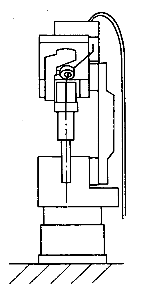
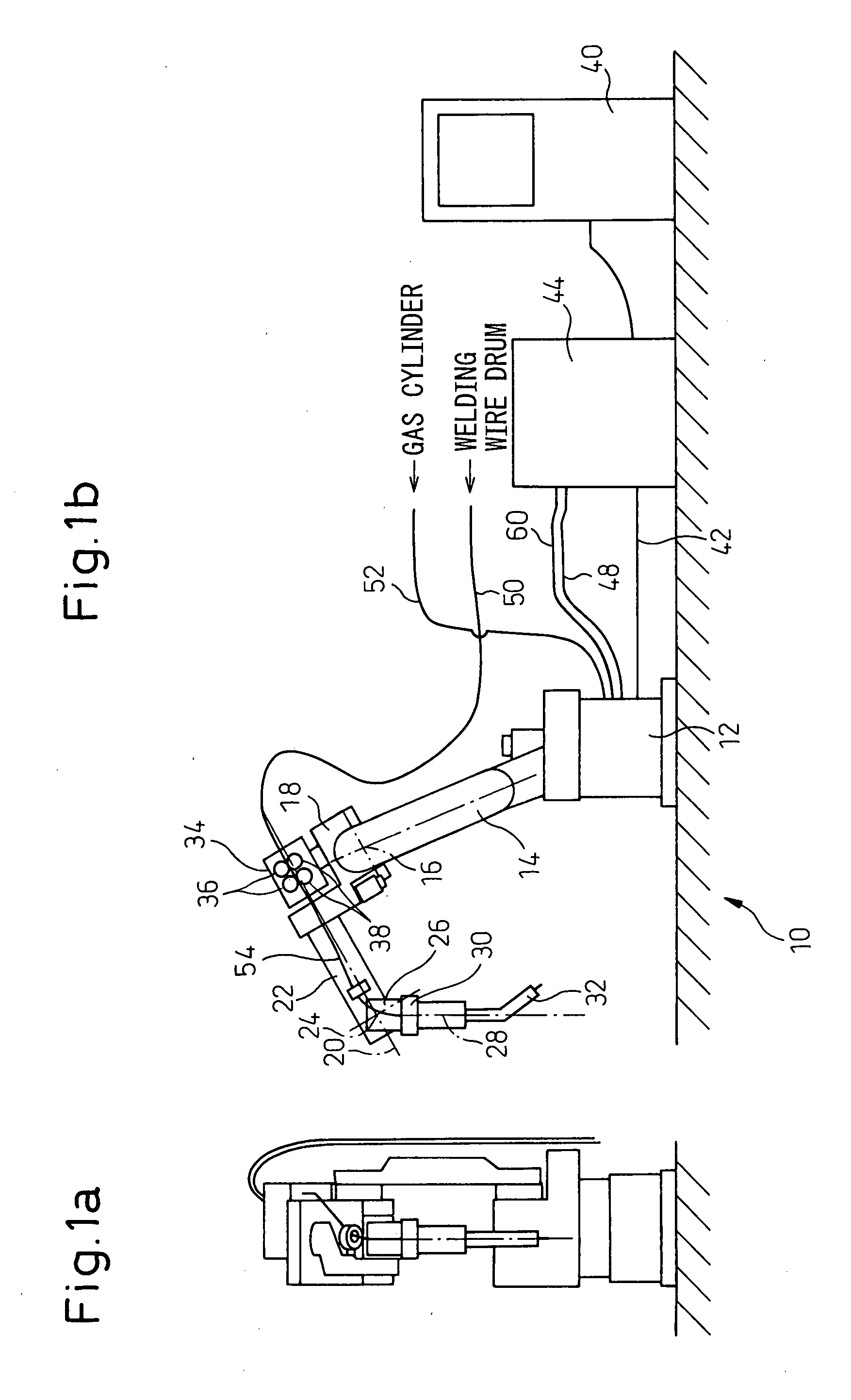
[0045]FIGS. 1a and 1b are front and right side views, respectively, of an industrial arc welding robot system having a welding torch as a work tool, as a robot arm drive mechanism according to the invention.

[0046] A robot 10 is an arc welding robot having six-degrees, having a base 12, an upper arm 14 arranged on the base 12, and a forearm 14 arranged on the front end of the upper arm 14 and rotatable about a first axis 16 generally perpendicular to the longitudinal direction of the upper arm 14. The forearm 18 has a first wrist element 22 mounted to the front end of the forearm and rotatable about a second axis 20 generally coinciding with the longitudinal direction of the forearm 18, a second wrist element 26 mounted to the front end of the first wrist element 22 and rotatable about a third axis 24 perpendicular to the second axis 20, and a third wrist element 30 mounted to front end of the second wrist element 26 and rotatable about a fourth axis 28 generally coinciding with the ...

second embodiment

[0072]FIGS. 13a and 13b are front and side views, respectively, showing a handling system 110 according to a robot system having an arm driving mechanism of the invention. In comparison with the welding robot 10 of FIG. 1, the wire feeder 34 is replaced with an electromagnetic valve box 134 containing an electromagnetic valve (not shown), and the welding torch 34 replaced with a hand 132. Accordingly, a signal line 148 and an air tube 152, as an umbilical member 154, are connected to the box 134. Also, between the hand 132 and the box 134, a signal line and an air tube are connected for controlling the hand 132 by means of the electromagnetic valve. A robot controller 140 controls the electromagnetic valve via the signal line 148, and the electromagnetic valve supplies air to the hand 132 corresponding to a signal. The hand has an adsorbing pad or an air gripper 133 attached thereto, configured to be driven by the supplied air, in order to adsorb or grip an object or a workpiece to ...


PUM


Abstract

A drive mechanism for an industrial robot arm, having a simple drive system, in which an extracting part of an umbilical member for a work tool is suitably positioned and a device for the work tool is positioned on the forearm so as not to project out, while the basic configuration of the robot arm may be similar to the prior art. A motor for a first wrist element is positioned in the area between a forearm and an upper arm such that the rotation axis of the motor is perpendicular to a second axis. Further, the motor is positioned at the point shifted toward the wrist element or a front end of the forearm, in relation to a first axis, along the longitudinal direction of the forearm. Therefore, a wide area for a wire feeder may be obtained above a bottom portion of the forearm.

Description

RELATED APPLICATIONS [0001] The present application claims priority from Japanese Patent Applications No. 2006-228081 and No. 2006-309396, filed on Aug. 24 and Nov. 15, 2006, respectively, the entire contents of which are fully incorporated herein by reference. BACKGROUND ART [0002] 1. Technical Field [0003] The preset invention relates to a drive mechanism used for an arm of an industrial robot. [0004] 2. Description of the Related Art [0005] When an industrial robot is used for an operation, the robot is required to be provided with an umbilical member including a cable and / or a tube for transmitting power or a signal to an end effector attached to the end of a wrist element of the robot. When the umbilical member is arranged around the wrist element of a robot arm, the umbilical member may come into contact with the arm or other equipment and may be worn or damaged. In order to avoid such a problem, several configurations has been proposed. [0006] For example, Japanese Unexamined...

Claims


Application Information

Patent Timeline
IPC IPC(8): B65H29/02B25J1/02
CPCB25J19/0029
Inventor INOUE, TOSHIHIKONAKAYAMA, KAZUTAKAIWAYAMA, TAKATOSHI
Owner FANUC LTD
Why Eureka
Try Eureka