
Ionically conductive composites for protection of active metal anodes

a technology of active metal anodes and composites, which is applied in the direction of non-aqueous electrolyte cells, cell components, cell component details, etc., can solve the problems of failure of rechargeable lithium metal batteries, and battery short circuit, etc., to achieve high overall ionic conductivity, facilitate manufacture, and high level of ionic conductivity

Inactive Publication Date: 2008-03-06
POLYPLUS BATTERY CO INC
View PDF99 Cites 57 Cited by
  • Summary
  • Abstract
  • Description
  • Claims
  • Application Information

AI Technical Summary

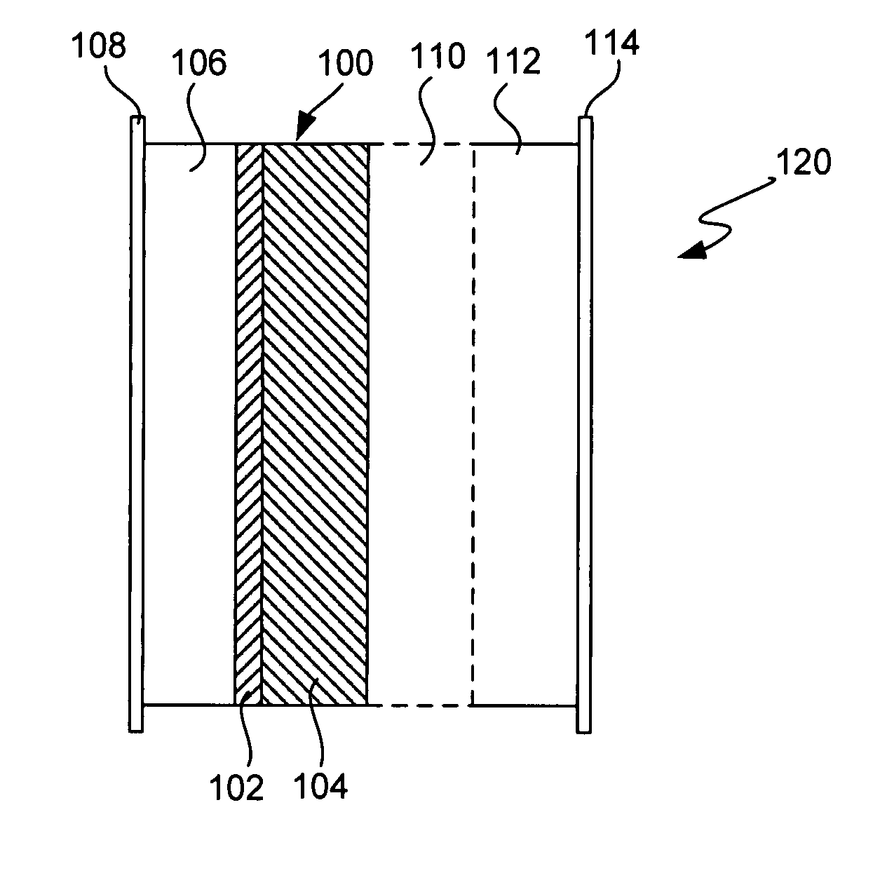
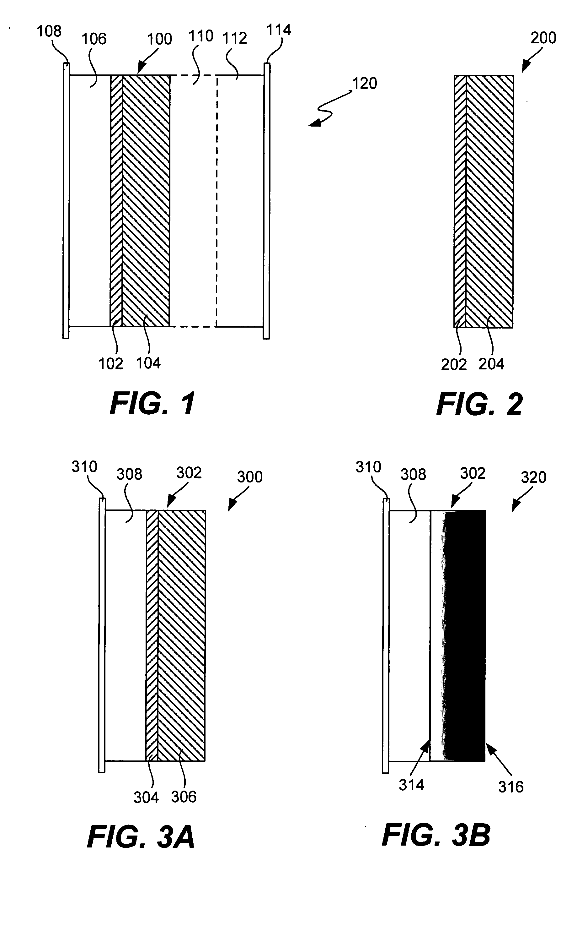
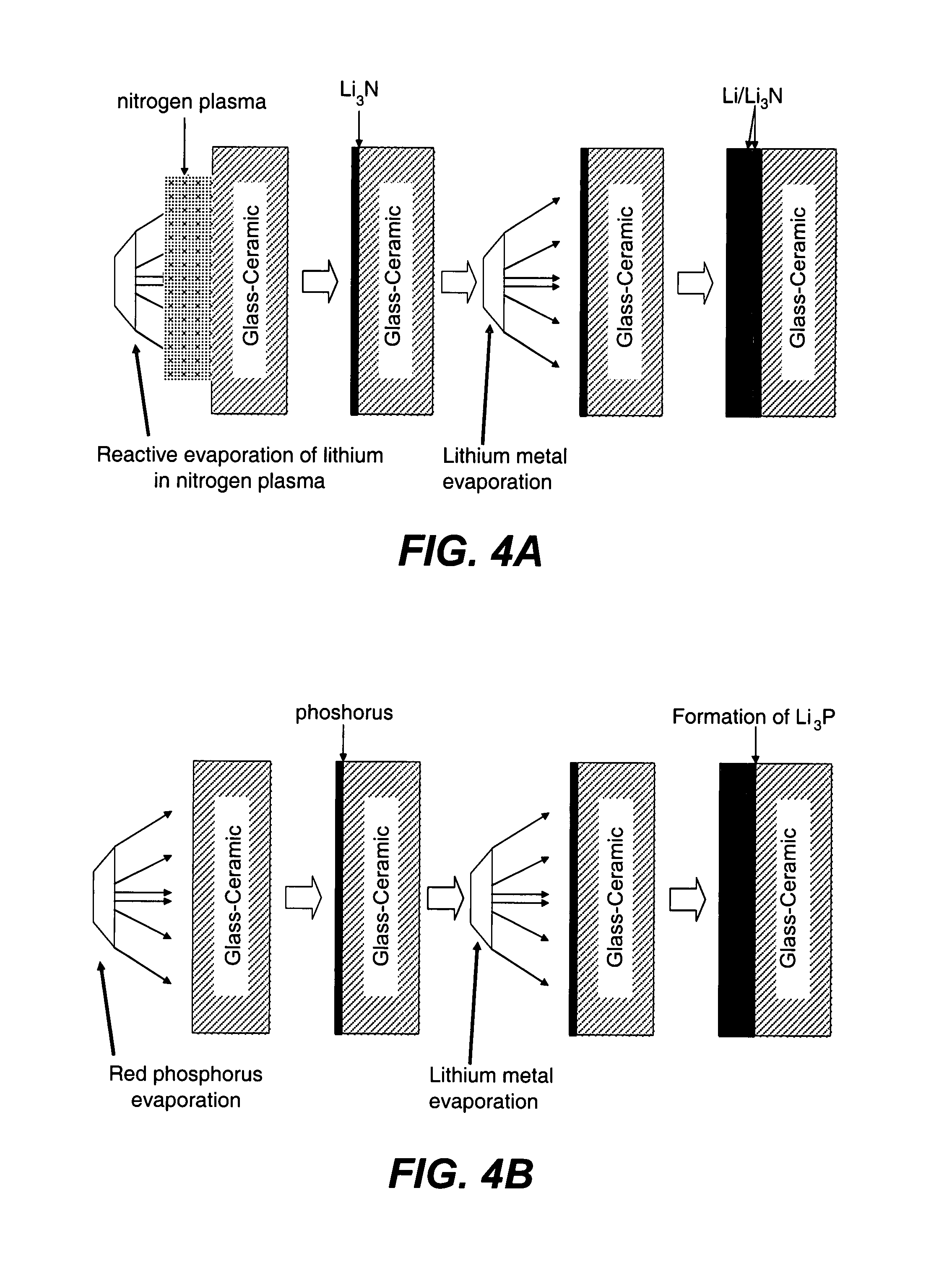
Benefits of technology

[0011] The present invention provides ionically conductive composites for protection of anodes and electrolytes and methods for their fabrication. The composites may be incorporated in active metal negative electrode (anode) structures and battery cells. In accordance with the invention, the properties of different ionic conductors are combined in a composite material that has the desired properties of high overall ionic conductivity and chemical stability towards the anode, the cathode and ambient conditions encountered in battery manufacturing. The composite is capable of protecting an active metal anode from deleterious reaction with other battery components or ambient conditions while providing a high level of ionic conductivity to facilitate manufacture and / or enhance performance of a battery cell in which the composite is incorporated.
[0012] The composite is composed of at least two components of different materials having different chemical compatibility requirements. The composite may be composed of a laminate of discrete layers of materials having different chemical compatibility requirements, or it may be composed of a gradual transition between layers of the materials. By “chemical compatibility” (or “chemically compatible”) it is meant that the referenced material does not react to form a product that is deleterious to battery cell operation when contacted with one or more other referenced battery cell components or manufacturing, handling or storage conditions. A first material layer (or first layer material) of the composite is ionically conductive, and chemically compatible with an active metal electrode material. Chemical compatibility in this aspect of the invention refers both to a material that is chemically stable and therefore substantially unreactive when contacted with an active metal electrode material. It may also refer to a material that is chemically stable with air, to facilitate storage and handling, and reactive when contacted with an active metal electrode material to produce a product that is chemically stable against the active metal electrode material and has the desirable ionic conductivity (i.e., a first layer material). Such a reactive material is sometimes referred to as a “precursor” material. A second material layer of the composite is substantially impervious, ionically conductive and chemically compatible with the first material. Additional layers are possible to achieve these aims, or otherwise enhance electrode stability or performance. All layers of the composite have high ionic conductivity, at least 10−7 S / cm, generally at least 10−6 S / cm, for example at least 10−5 S / cm to 10−4 S / cm, and as high as 10−3 S / cm or higher so that the overall ionic conductivity of the multi-layer protective structure is at least 10−7 S / cm and as high as 10−3 S / cm or higher.
[0017] A suitable second layer may include a polymer component to enhance its properties. For example, a glass-ceramic active metal ion conductor, like the glass-ceramic materials described above, may also be combined with polymer electrolytes to form flexible composite sheets of material which may be used as second layer of the protective composite. One important example of such a flexible composite material has been developed by OHARA Corp. (Japan). It is composed of particles of a Li-ion conducting glass-ceramic material, such as described above, and a solid polymer electrolyte based on PEO-Li salt complexes. OHARA Corp. manufactures this material in the form of sheet with a thickness of about 50 microns that renders it flexible while maintaining its high ionic conductivity. Because of its relatively high ionic conductivity (better than 4*10−5 S / cm at room temperature in the case of the OHARA product) and stability toward metallic Li, this type of composite electrolyte can be used at room temperature or elevated temperatures in fully solid-state cells.

Problems solved by technology

Unfortunately, no rechargeable lithium metal batteries have yet succeeded in the market place.
The failure of rechargeable lithium metal batteries is largely due to cell cycling problems.
This causes an internal short circuit in the battery, rendering the battery unusable after a relatively few cycles.
While cycling, lithium electrodes may also grow “mossy” deposits which can dislodge from the negative electrode and thereby reduce the battery's capacity.
Many techniques for applying protective layers have not succeeded.
Thus, they fail to adequately protect the lithium electrode.

Method used


Image

  • Ionically conductive composites for protection of active metal anodes
  • Ionically conductive composites for protection of active metal anodes
  • Ionically conductive composites for protection of active metal anodes

Examples


example 1

Impedance Measurements Using LIPON in Composite Protective Layer

[0082] Approximately 0.75 microns of LiPON was RF sputter-deposited onto copper foil samples in a MRC 8671 Sputter Deposition system. Some of the copper foil samples were coated with an additional layer of Cu3N (approximately 0.9 microns) by RF Magnetron sputtering of a copper target in a nitrogen environment. One LiPON / Cu sample was transferred to a vacuum evaporator, and approximately 3 to 7 microns of lithium metal was evaporated directly onto the LiPON surface. Another Cu3N / LiPON / Cu sample was coated with a similar thickness of lithium. The impedance for the unprotected LiPON / Cu sample is shown in FIG. 7A; the evaporation of lithium onto the LiPON surface led to a dramatic rise in the resistance of the sample, which is undesirable for electrochemical devices. The beneficial effects of the protective Cu3N film is seen in FIG. 7B; the impedance is dramatically lower in this case.

example 2

Impedance Measurements Using Glass-Ceramic Active Metal Ion Conductor (OHARA) in Composite Protective Layer

[0083] Samples of Li+ conductive glass-ceramic plates were received from OHARA Corporation. Approximately 3 to 7 microns of lithium was evaporated directly onto the OHARA glass-ceramic plate. The deleterious reaction of lithium with the electrolyte is seen in FIG. 8A; the impedance of the sample is quite large, approximately 40,000 Wcm2. Onto a second sample of glass-ceramic plate was RF Magnetron sputter-deposited a film of Cu3N (˜0.9 microns thick), with subsequent evaporation of about 3 to 7 microns of lithium. The beneficial effect of the Cu3N film can be seen in FIG. 8B; the impedance of the glass-ceramic is dramatically improved relative to the plate without the Cu3N film. Superimposition of FIGS. 8A and 8B in FIG. 8C further illustrates the dramatic improvement in performance for the Cu3N protected plate. The ionically conductive nature of the protective film is seen in...


PUM

PropertyMeasurementUnit
ionic conductivityaaaaaaaaaa

Abstract

Disclosed are ionically conductive composites for protection of active metal anodes and methods for their fabrication. The composites may be incorporated in active metal negative electrode (anode) structures and battery cells. In accordance with the invention, the properties of different ionic conductors are combined in a composite material that has the desired properties of high overall ionic conductivity and chemical stability towards the anode, the cathode and ambient conditions encountered in battery manufacturing. The composite is capable of protecting an active metal anode from deleterious reaction with other battery components or ambient conditions while providing a high level of ionic conductivity to facilitate manufacture and / or enhance performance of a battery cell in which the composite is incorporated.

Description

CROSS-REFERENCE TO RELATED APPLICATIONS [0001] This application is a continuation of U.S. patent application Ser. No. 10 / 731,771 filed Dec. 5, 2003, titled IONICALLY CONDUCTIVE COMPOSITES FOR PROTECTION OF ACTIVE METAL ANODES, now pending, which in turn is a continuation-in-part of U.S. patent application Ser. No. 10 / 686,189 filed Oct. 14, 2003, titled IONICALLY CONDUCTIVE COMPOSITES FOR PROTECTION OF ACTIVE METAL ANODES, now pending, which claims priority to U.S. Provisional Patent Application No. 60 / 418,899 filed Oct. 15, 2002, titled IONICALLY CONDUCTIVE COMPOSITES FOR PROTECTION OF ANODES AND ELECTROLYTES. These prior applications are incorporated herein by reference in their entirety for all purposes.BACKGROUND OF THE INVENTION [0002] 1. Field of the Invention [0003] The present invention relates generally to separators and electrode structures for use in batteries. More particularly, this invention relates composites for protection of active metal anodes from deleterious react...

Claims


Application Information

Patent Timeline
Patent Type & Authority Applications(United States)
IPC IPC(8): H01M2/16H01M50/489H01M50/497
CPCC03C4/18Y02E60/122H01M2/16H01M2/1673H01M4/134H01M4/366H01M4/38H01M6/18H01M6/181H01M6/182H01M6/185H01M6/187H01M6/188H01M10/052H01M10/0525H01M10/056H01M10/0562H01M10/0565H01M10/0583H01M2004/021H01M2300/0065H01M2300/0094C03C10/00Y02E60/10H01M50/46H01M50/489H01M50/497
Inventor VISCO, STEVEN J.NIMON, YEVGENIY S.KATZ, BRUCE D.
Owner POLYPLUS BATTERY CO INC
Learn More