Eureka AIR delivers breakthrough ideas for toughest innovation challenges, trusted by R&D personnel around the world.

Conductive porous materials

a porous material and conductive technology, applied in the field of flexible substrates for electrical circuits, can solve the problems of excessive degradation of electrical conductivity, high surface porosity of conventional printed circuit configurations formed on substrates with high porosity,

Inactive Publication Date: 2008-03-06
KIMBERLY-CLARK WORLDWIDE INC
View PDF33 Cites 37 Cited by
  • Summary
  • Abstract
  • Description
  • Claims
  • Application Information

AI Technical Summary

Benefits of technology

[0005]By incorporating its various aspects and features, the method can provide a more effective printing of electrical conductors on porous or semi-porous, materials with a reduced loss of conductivity. The method can help form a flexible continuous base region to support electrical connections with more uniform electrical continuity. Additionally, the method can be more readily employed with ordinary ink formulations, and with ordinary printing equipment.

Problems solved by technology

Conventional printed circuit configurations formed on substrates having high levels of surface porosity, however, have continued to exhibit problems.
When the conductive inks have been printed on porous materials, the level of electrical conductivity has been excessively degraded.

Method used


Image

  • Conductive porous materials
  • Conductive porous materials
  • Conductive porous materials

Examples


Embodiment Construction

[0014]It should be noted that, when employed in the present disclosure, the terms “comprises”, “comprising” and other derivatives from the root term “comprise” are intended to be open-ended terms that specify the presence of any stated features, elements, integers, steps, or components, and are not intended to preclude the presence or addition of one or more other features, elements, integers, steps, components, or groups thereof.

[0015]By the terms “particle,”“particles,”“particulate,”“particulates” and the like, it is meant that the material is generally in the form of discrete units. The units can comprise granules, powders, spheres, pulverized materials or the like, as well as combinations thereof. The particles can have any desired shape such as, for example, cubic, rod-like, polyhedral, spherical or semi-spherical, rounded or semi-rounded, angular, irregular, etc. Shapes having a large greatest dimension / smallest dimension ratio, like needles, flakes and fibers, are also contem...


PUM

PropertyMeasurementUnit
melting point temperatureaaaaaaaaaa
particle sizeaaaaaaaaaa

Abstract

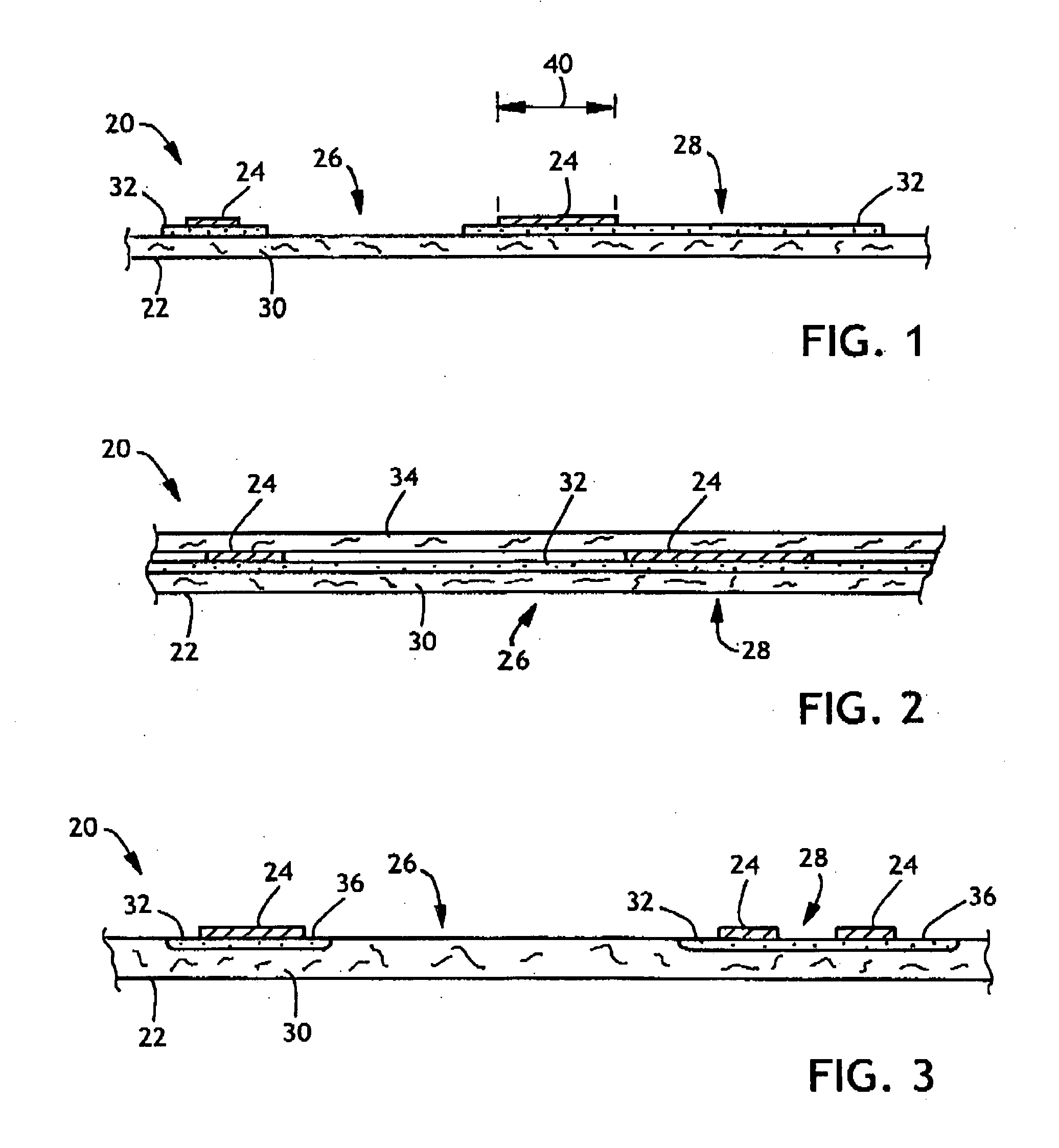
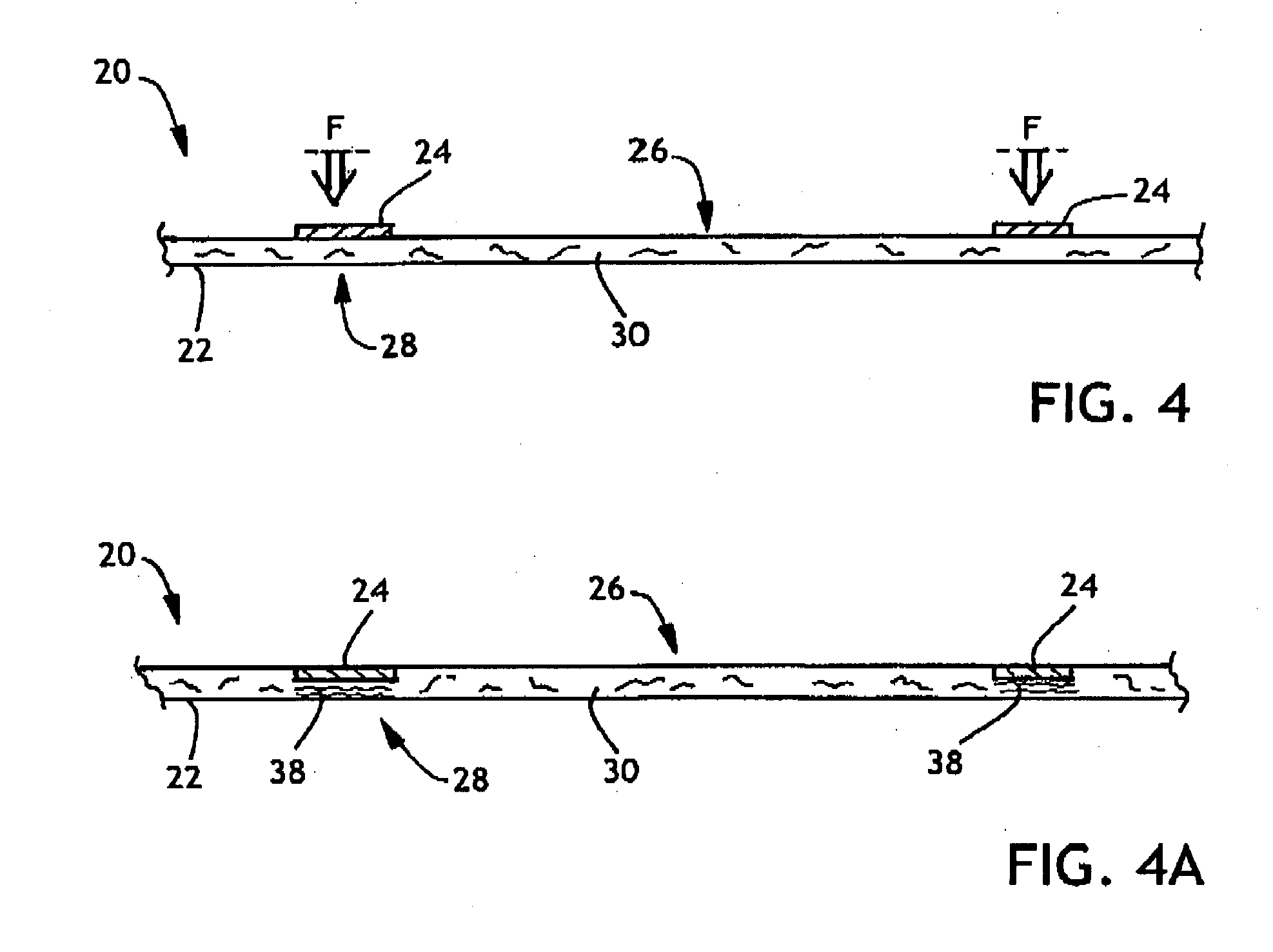
A limited use, disposable article (20), comprises a matrix-substrate (22), and an electrically-conductive region (24) of a separately provided, electrically-conductive material that has been operatively applied to the matrix-substrate from a viscous configuration of the electrically-conductive material. The matrix-substrate includes a first matrix-region (26), and at least a second matrix-region (28). At least the second matrix-region (28) can include a treatment that provides for an operative formation of a selected resistivity in the electrically-conductive region. The first matrix-region (26) has a high resistivity, and the electrically-conductive region (24) is positioned operatively adjacent the second matrix-region (28). The electrically-conductive region (24) has a low resistivity, as determined when the electrically-conductive region is positioned operatively adjacent the second matrix-region and configured for its intended use.

Description

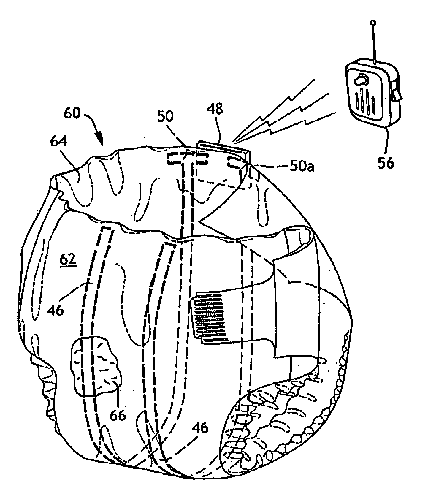
FIELD OF THE INVENTION[0001]The present invention relates to electrical circuits formed on a flexible substrate. More particularly, the present invention pertains to electrical circuits formed on a substrate having a high degree of surface porosity.BACKGROUND OF THE INVENTION[0002]Electrical circuits have been printed or otherwise applied to flexible substrates, such as paper, woven fabrics, nonwoven fabrics and polymer films. The electrical circuits have incorporated conductive inks applied with various ink-printing techniques, and various products, such as covers, badges, labels and tags, have incorporated the printed circuits. In particular arrangements, the printed circuits have been employed in hygienic products, such as drapes, gowns, garments, personal care absorbent products, and the like. In other arrangements, electrical / electronic circuitry has been employed to provide sensors located in selected personal care products, such as wetness sensors in disposable infant diapers...

Claims


Application Information

Patent Timeline
Patent Type & Authority Applications(United States)
IPC IPC(8): A61F13/15
CPCA61F13/42A61F2013/8473A61F13/84Y10T442/68A61F13/53
Inventor TIPPEY, DAROLD DEANALES, THOMAS MICHAEL
Owner KIMBERLY-CLARK WORLDWIDE INC
Why Eureka
Eureka Blog
Learn More