Bulk supply apparatus and method for cleaning a combustion engine system

a technology for combustion engines and equipment, applied in the direction of cleaning process and equipment, chemistry apparatus and processes, etc., can solve the problems of needing to clean, the catalytic converter does not clog or become contaminated during use, and the failure to clean other important operating components of the gasoline engine, etc., to achieve the effect of improving the flow of exhaus

Inactive Publication Date: 2008-03-13
ESTERLINE OLEN C
View PDF5 Cites 13 Cited by
  • Summary
  • Abstract
  • Description
  • Claims
  • Application Information

AI Technical Summary

Benefits of technology

[0015]Intake and combustion chamber flush is introduced through a vacuum intake line through the intake manifold of the injector base. The flow rate is regulated. This results in clean injectors and a cleaner catalytic converter.
[0016]Finally, a fuel injector system cleaner is introduced into the gas tank. This scavenges and emulsifies water due to condensation and polar deposits in the fuel delivery system and injectors. As the cleaner passes through the engine, the various components thereof are cleaned. As the chemicals gasify and pass through the catalytic converter, clogging creosote deposits are released to improve the flow of exhaust through the system.

Problems solved by technology

Additives are available to one to introduce into an engine to partly clean the engine; however, an automobile owner may add an additive to the gasoline tank upon fill-up and completely fail to clean other important operating components of a gasoline engine.
The catalytic converter does clog or become contaminated during use and needs to be cleaned.

Method used


Image

  • Bulk supply apparatus and method for cleaning a combustion engine system
  • Bulk supply apparatus and method for cleaning a combustion engine system
  • Bulk supply apparatus and method for cleaning a combustion engine system

Examples


Embodiment Construction

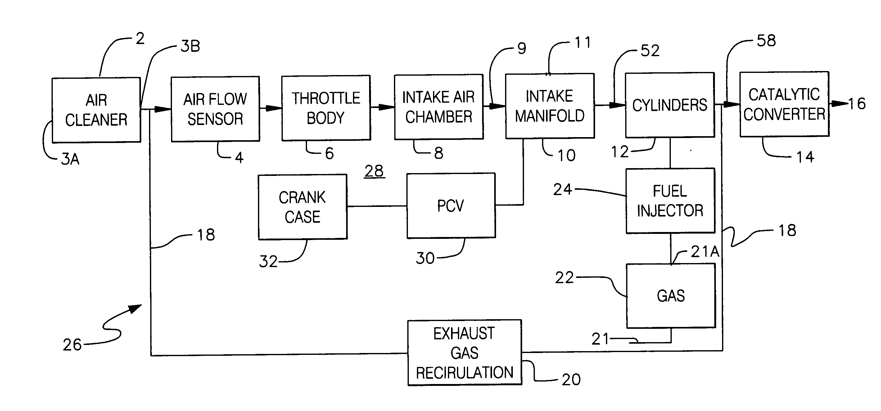
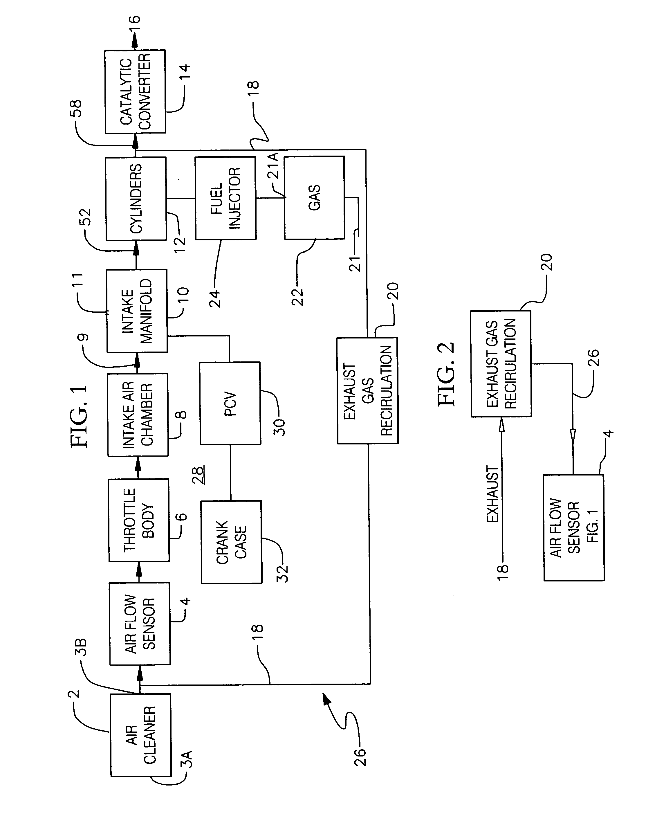
[0042]Referring to FIG. 1, there is disclosed a block diagram of the basic components of a combustion engine. Typically, air enters through air cleaner 2 and then proceeds through a Mass Air Flow Sensor 4, then through a throttle body 6 and then through an Intake Air Chamber 8, then through an Intake Manifold 10 and then through Cylinder 12 and then through a Catalytic Converter and then exhaust into atmosphere 16.

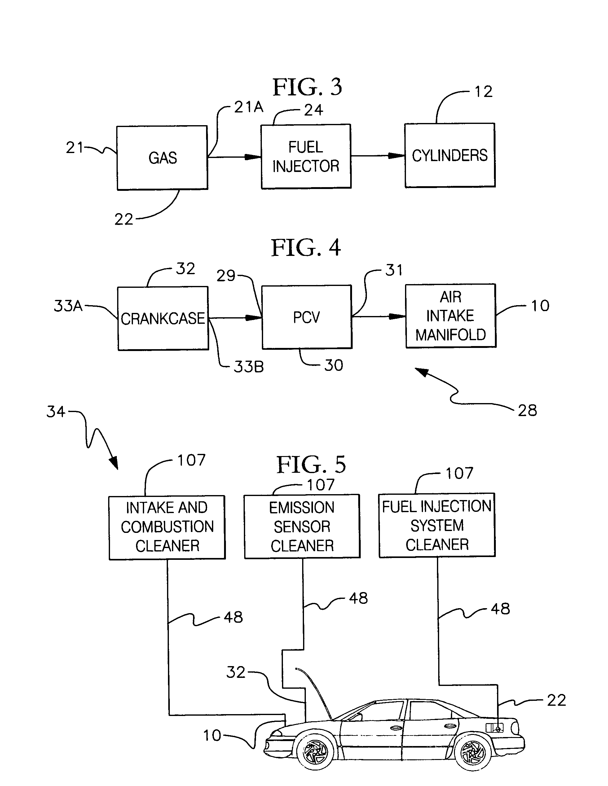
[0043]Fuel from fuel tank 22 is supplied through fuel injector 24 into cylinder 12 where the fuel is burned.

[0044]Exhaust leaving cylinder 12 is also caused to pass through an Exhaust Gas Recirculation (EGR) System 20 and introduced into the air supply entering through air cleaner 2 as is well known in combustion engines as disclosed herein above.

[0045]FIG. 2 discloses exhaust gas re-circulation system 20 as being disposed in the exhaust system so that exhaust gas re-circulation system 20 causes some of the exhaust from the combustion engine to be directed back into the ai...


PUM


Abstract

A method and apparatus for cleaning a combustion engine having, an intake and combustion chamber having a fuel injector injection device, an oil lubrication system, a catalytic converter and a fuel supply tank. Various solvents are introduced from bulk supply sources into the crank case and into the combustion chamber and into the fuel supply to clean an engine by the introduction of predetermined solvents in a predetermined sequence to clean the engine, the fuel supply tank, the oil lubrication system and the catalytic converter. As chemicals gasify and pass through the catalytic converter, clogging creosote deposits are released thus improving the flow of exhaust through the system improving efficiency and gas mileage.

Description

BACKGROUND OF THE INVENTION[0001]1. Field of the Invention[0002]The present invention relates to a method and apparatus for cleaning a combustion engine having, an intake and combustion chamber having a fuel injector injection device, an oil lubrication system, a catalytic converter and a fuel supply tank. Various solvents are introduced from bulk supply sources into the crank case and into the combustion chamber and into the fuel supply to clean an engine by the introduction of predetermined solvents in a predetermined sequence to clean the engine, the fuel supply tank, the oil lubrication system and the catalytic converter. As chemicals gasify and pass through the catalytic converter, clogging creosote deposits are released thus improving the flow of exhaust through the system improving efficiency and gas mileage.[0003]2. Description of Related Art[0004]Additives are available to one to introduce into an engine to partly clean the engine; however, an automobile owner may add an ad...

Claims


Application Information

Patent Timeline
Patent Type & Authority Applications(United States)
IPC IPC(8): B08B3/00B08B9/00B08B3/12
CPCB08B3/00F02B77/04B08B9/00
Inventor ESTERLINE, OLEN C.
Owner ESTERLINE OLEN C
Why Eureka
Try Eureka