High Purity Hydrogen and Electric Power Co-Generation Apparatus and Method

a high-purity hydrogen and electric power co-generation technology, applied in electrochemical generators, instruments, energy inputs, etc., can solve the problems of complex problems associated with hydrogen production and storage, insufficient current infrastructure for hydrogen production, storage and delivery, and requiring both heat and electric power inputs, etc., to achieve high-purity hydrogen and electricity.

Active Publication Date: 2008-03-13
COORSTEK INC
View PDF4 Cites 33 Cited by
  • Summary
  • Abstract
  • Description
  • Claims
  • Application Information

AI Technical Summary

Problems solved by technology

Many expect fuel cells to be an important component in establishing a “hydrogen economy.” Unfortunately, the present infrastructure for production, storage, and delivery of hydrogen is currently vastly inadequate to support a hydrogen economy.
Furthermore, problems associated with hydrogen production and storage are complicated by the fact that some fuel cell technologies require ultra-high purity hydrogen to operate effectively.
Although hydrogen for use in PEM fuel cells may be derived from hydrocarbon fuels, this method of production typically requires complex chemical processing equipment to remove carbon monoxide and / or carbon dioxide to produce hydrogen with sufficient purity for PEM applications.
This method, however, requires both heat and electric power inputs.
Although the performance of SOFCs continues to improve at temperatures above 800 to 850° C., SOFCs begin to degrade rapidly as operating temperatures increase beyond these levels.
This generally requires expensive heat exchangers to pre-heat the large airflow through the SOFCs.
These heat exchangers are typically a large part of the total system cost of conventional SOFCs.

Method used


Image

  • High Purity Hydrogen and Electric Power Co-Generation Apparatus and Method
  • High Purity Hydrogen and Electric Power Co-Generation Apparatus and Method
  • High Purity Hydrogen and Electric Power Co-Generation Apparatus and Method

Examples


Embodiment Construction

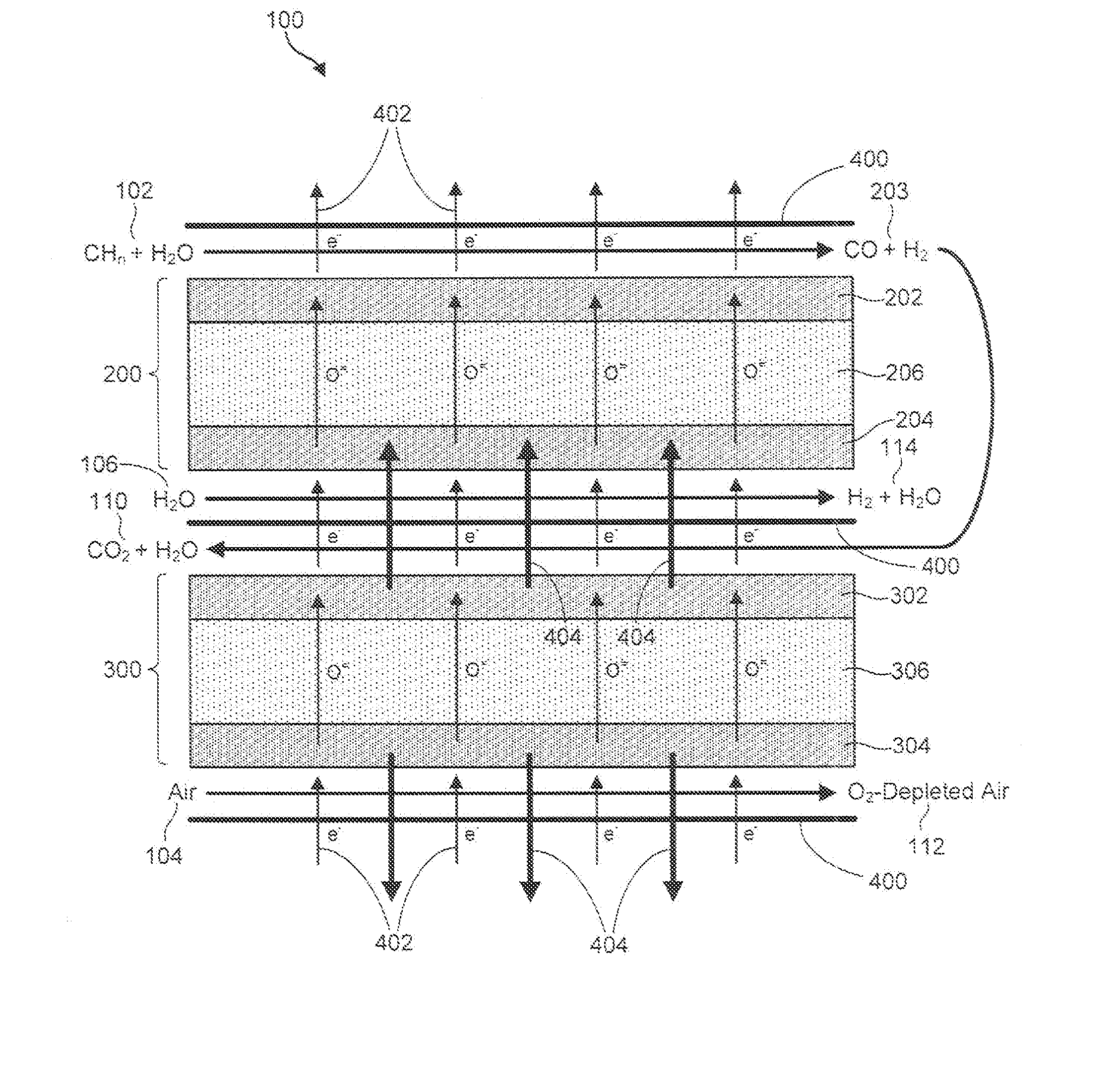
[0027] It will be readily understood that the components of the present invention, as generally described and illustrated in the Figures herein, could be arranged and designed in a wide variety of different configurations. Thus, the following more detailed description of the embodiments of the invention, as represented in the Figures, is not intended to limit the scope of the invention, as claimed, but is merely representative of certain examples of presently contemplated embodiments in accordance with the invention. The presently described embodiments will be best understood by reference to the drawings, wherein like parts are designated by like numerals throughout.

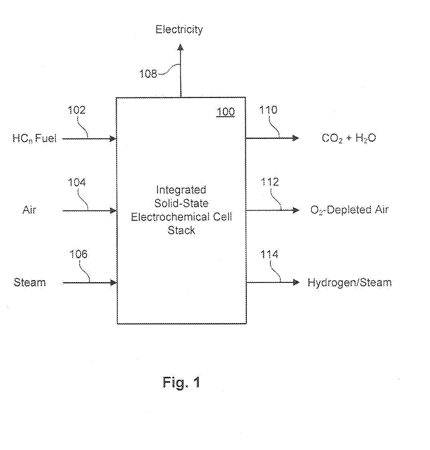
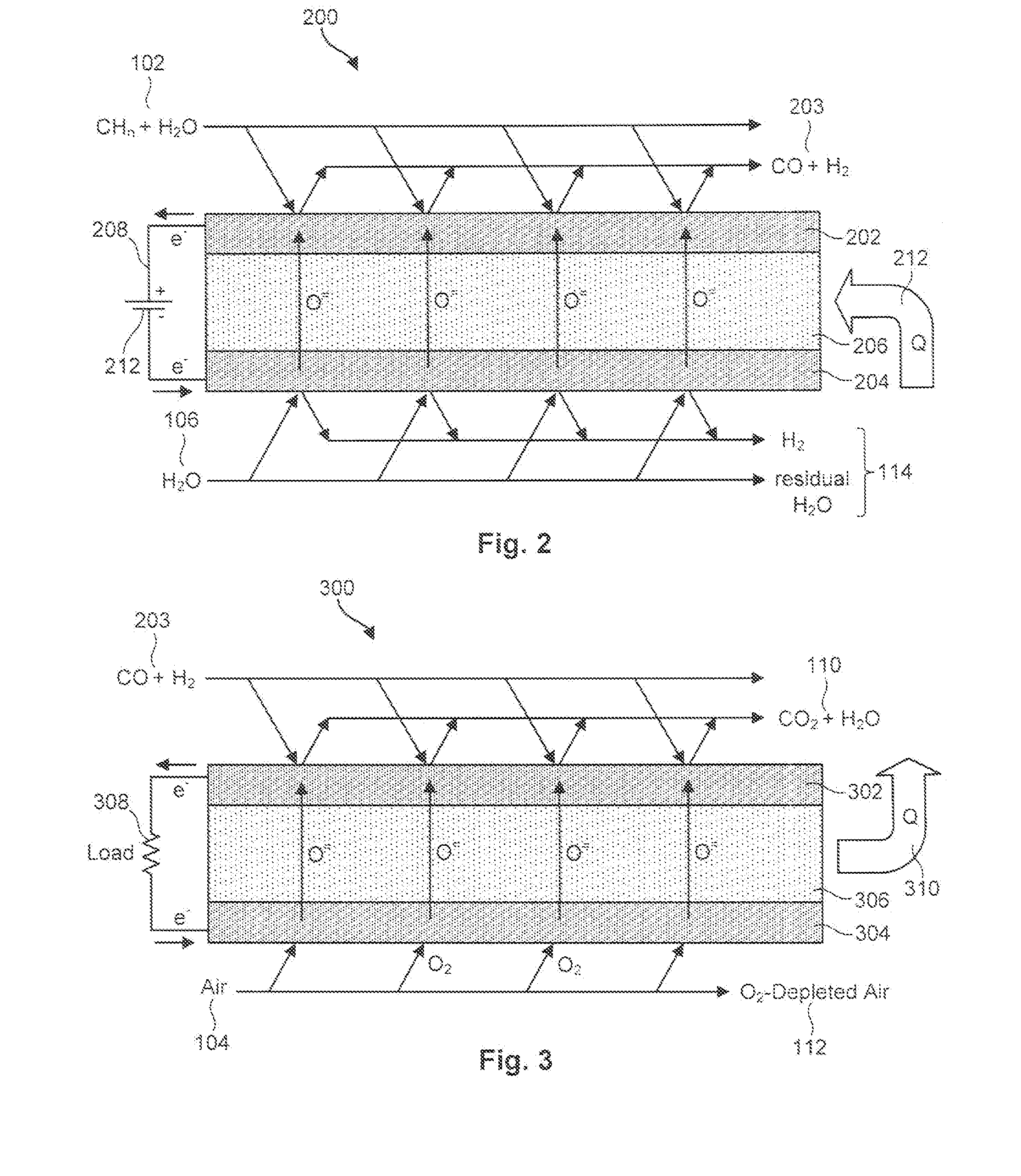
[0028] Referring to FIG. 1, in general, an integrated solid-state electrochemical cell stack 100 in accordance with the invention may be configured to receive as inputs a hydrocarbon fuel 102 such as natural gas, methane, propane, butane, or the like; an oxygen-containing gas stream 104 such as air, and an oxygen-contai...


PUM

PropertyMeasurementUnit
temperaturesaaaaaaaaaa
open circuit voltageaaaaaaaaaa

Abstract

An apparatus to produce high purity hydrogen and electricity is disclosed in one embodiment of the invention as including a fuel cell configured to convert the chemical energy of a fuel to electricity and heat. An electrolyzer cell is placed in electrical and thermal communication with the fuel cell and is configured to electrolyze an oxygen-containing compound, such as steam or carbon dioxide, using the electricity and heat generated by the fuel cell. In selected embodiments, the fuel cell and electrolyzer cell are physically integrated into a single electrochemical cell stack.

Description

RELATED APPLICATIONS [0001] This application claims priority to U.S. Provisional Patent No. 60 / 825,571 filed on Sep. 13, 2006 and entitled CO-GENERATION OF HIGH PURITY HYDROGEN AND ELECTRIC POWER.BACKGROUND OF THE INVENTION [0002] 1. Field of the Invention [0003] This invention relates to fuel cells and high temperature steam electrolysis, and more particularly to apparatus and methods for integrating fuel cell and high temperature steam electrolysis technology. [0004] 2. Description of the Related Art [0005] There is a great deal of interest in hydrogen technologies such as fuel cells to reduce emissions and dependence on fossil fuels. Many expect fuel cells to be an important component in establishing a “hydrogen economy.” Unfortunately, the present infrastructure for production, storage, and delivery of hydrogen is currently vastly inadequate to support a hydrogen economy. Furthermore, problems associated with hydrogen production and storage are complicated by the fact that some ...

Claims


Application Information

Patent Timeline
Patent Type & Authority Applications(United States)
IPC IPC(8): C25B9/00C25B1/02C25B9/18
CPCC25B1/02C25B9/00H01M8/0254H01M8/0618H01M8/0656Y02E60/525H01M8/241H01M8/2425H01M2008/1095H01M2008/1293Y02E60/528H01M8/184H01M8/2432H01M8/2457Y02E60/50Y02P20/129
Inventor HARTVIGSEN, JOSEPH J.
Owner COORSTEK INC
Why Eureka
Try Eureka