Method and apparatus for mitigating trailing vortex wakes of lifting or thrust generating bodies

a technology of trailing vortex and trailing vortex, which is applied in the field of fluid dynamics, can solve the problems of inconvenience for passengers, increased burden on already congested and constrained airports and aviation operator terminal areas, and large separation distance between aircraft, so as to reduce the size, reduce the size, and reduce the effect of wake perturbation

Active Publication Date: 2008-03-13
DELOS AEROSPACE
View PDF15 Cites 148 Cited by
  • Summary
  • Abstract
  • Description
  • Claims
  • Application Information

AI Technical Summary

Benefits of technology

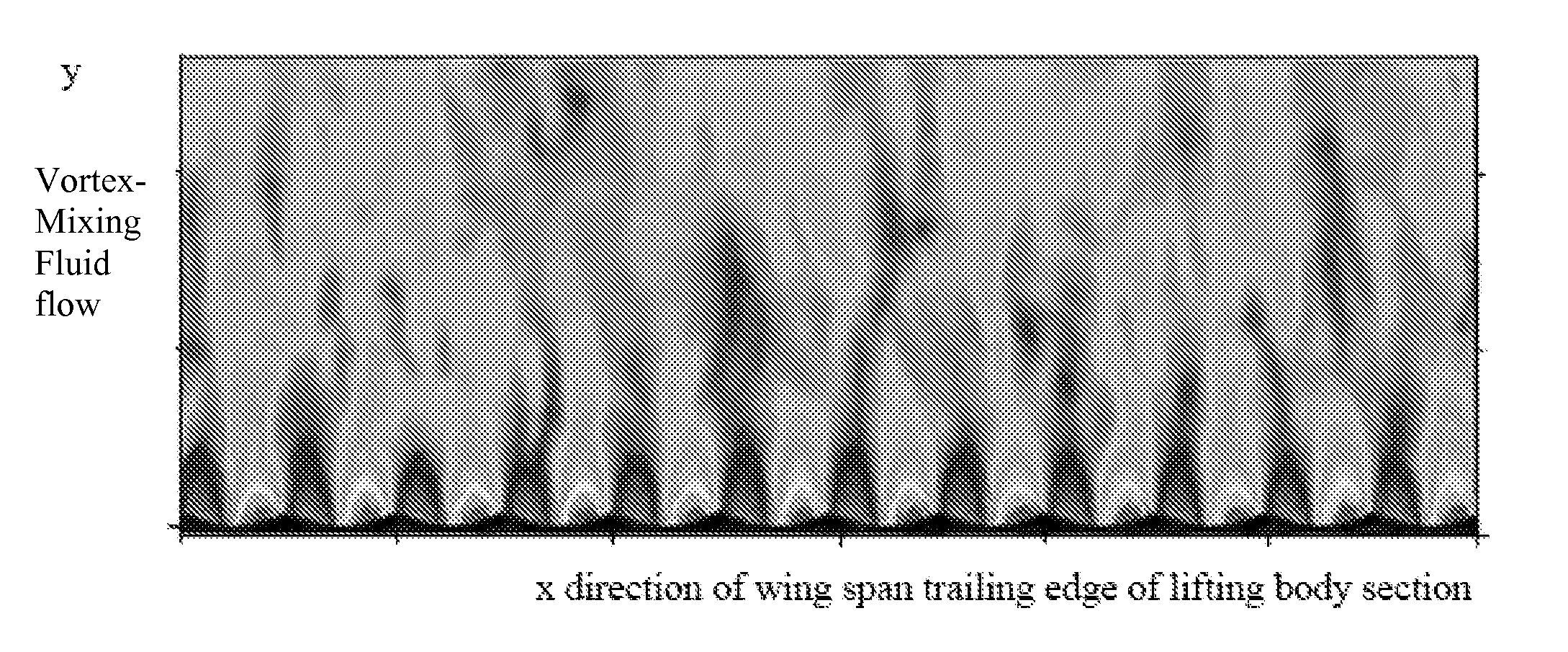
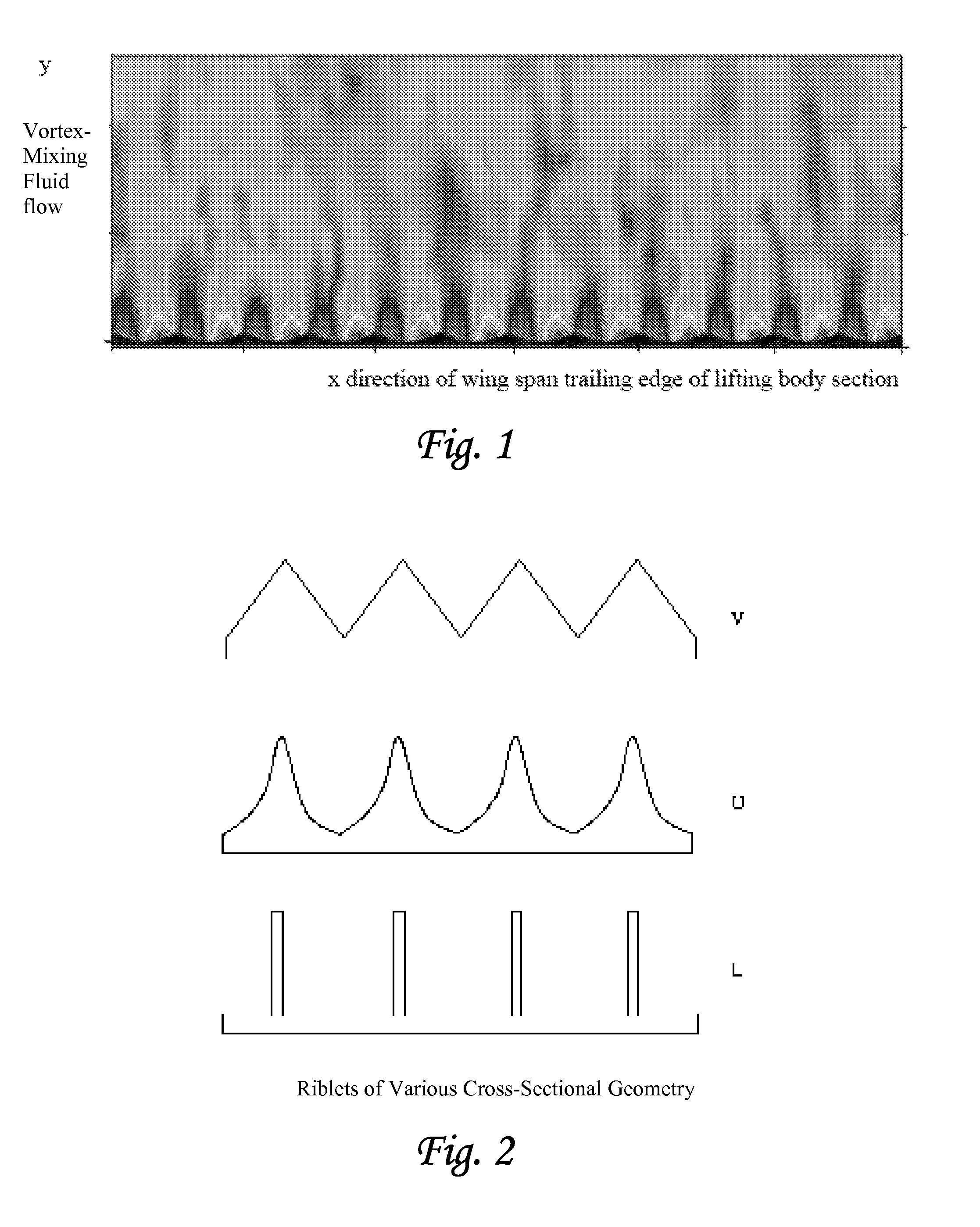
[0014] Accordingly, it is an object of the invention to provide an improved system and method for control of trailing wake vortex structures called “vortex-mixing” that include; design of riblets and / or compliant surfaces combined with lifting or thrust-generating body trailing edge shapes that vary across the trailing edge for deflectable and / or non-deflectable surfaces that produce smaller wake vortex perturbations along the entire lifting or thrust-generating body span structure. These contour shaped lifting or thrust-generating bodies combined with various combinations of riblet and / or compound riblet and / or shaped riblets and / or compliant surfaces, promote chord wise fluid flow and exploit the mixing of the lower fluid stream and upper fluid stream of the lifting or thrust-generating surface or other surfaces such that the time and position of the fluid stream mixing is varied across the span of lifting or thrust-generating body trailing edge thus reducing the size and duration of the trailing wake vortex structures generated from said lifting or thrust generating body thus allowing for high-force, high-deflection capabilities of deflectable surfaces which have proved to be well suited for the requirements of mitigating the concentrated trailing wake vortex structures generated by lifting or thrust-generating bodies at the lifting or thrust generating body within the root and tip region.
[0015] Further, it is an object of the invention to provide an improved system and method for decreased drag on static structures that include; design of shapes that vary across the three dimensions of the static body that produce smaller wake perturbations. These contour shaped bodies, exploit the structures used in the lifting or thrust-generating surface such that the time and position of the fluid stream mixing is varied across the static bodies trailing edge thus reducing the size and energy of the wake generated from said static bodies thus allowing for a reduced drag, which have proved to be well suited for the requirements of static structures such as oil rigs, pipe structures, bridges and, buildings.
[0016] Further, various methods that promote mixing using corrugated, serrated or convoluted surfaces or control surfaces can be combined with contour surface geometries to form new advanced surfaces that promotes the vortex-mixing system and method.

Problems solved by technology

The standard procedure in air flight control is to stagger aircraft flight patterns so that the trailing wake vortices have dissipated by the time another aircraft passes through the same area, but since wake vortices can maintain their structure for a long period of time over miles, the required separation distance between aircraft is large.
Aviation operations are predicted to continue to rise steadily in traffic volume, increasing the burden on already congested and constrained airports and aviation operator terminal areas.
Airspace congestion has led to delays that inconvenience passengers, cost the aviation industry hundreds of millions of dollars each year, and will eventually limit growth capacity.
The FAA mandated separation distances between aircraft are a major challenge to alleviating airspace congestion.
A major factor governing the safe, minimum separation distance is the hazard generated by the long-lived concentrated wake vortex structures of a preceding aircraft.

Method used


Image

  • Method and apparatus for mitigating trailing vortex wakes of lifting or thrust generating bodies
  • Method and apparatus for mitigating trailing vortex wakes of lifting or thrust generating bodies
  • Method and apparatus for mitigating trailing vortex wakes of lifting or thrust generating bodies

Examples


Embodiment Construction

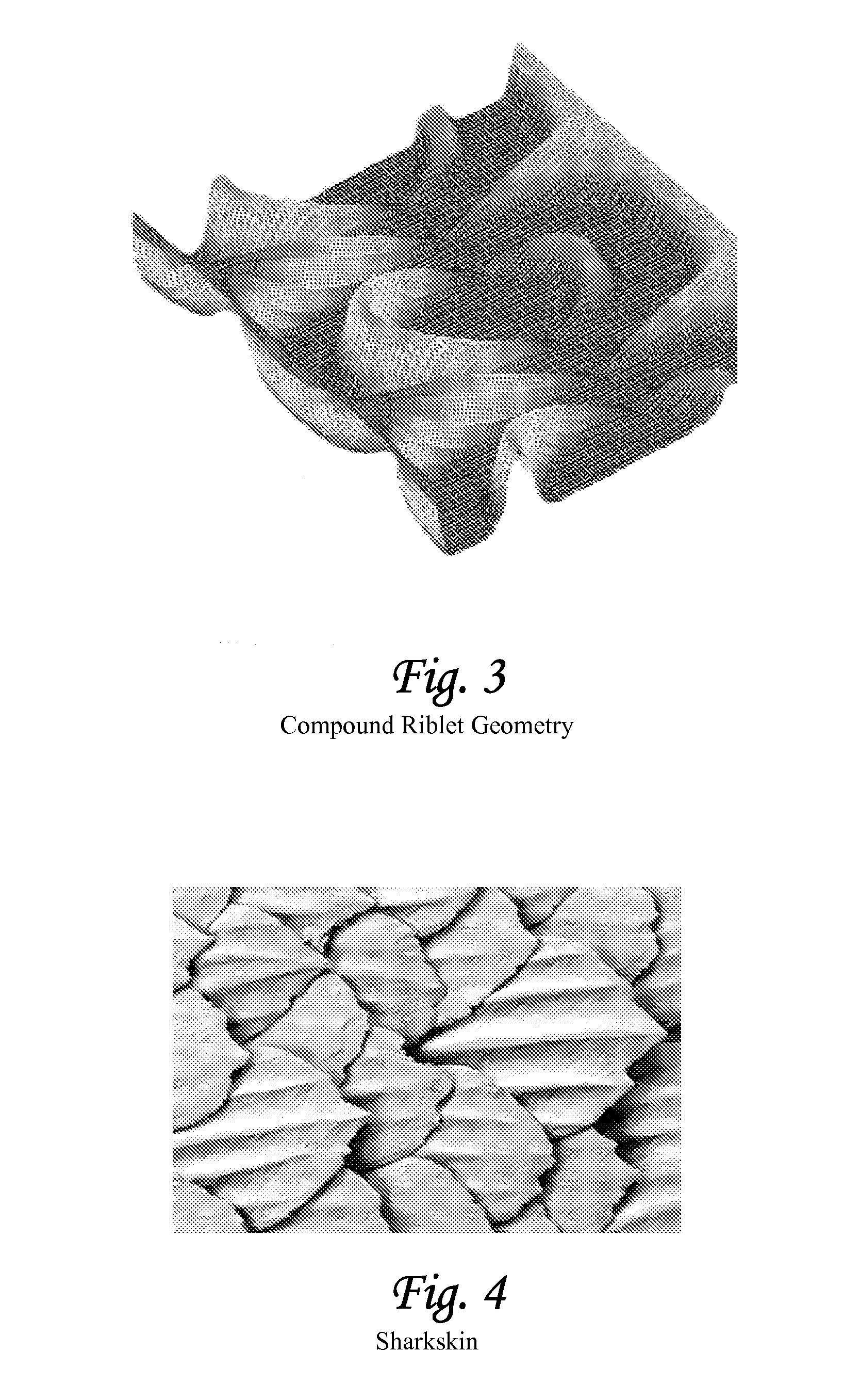
[0045] The invention relates to lifting and / or thrust-generating bodies and / or surfaces which reduce the intensity of and the associated induced drag caused by the concentrated and long-lived trailing wake vortex structures generated at the root and tip region of finite span lifting or thrust-generating bodies or other surfaces by means of three-dimensional (x, y and z) contour surface geometries combined with surface treatments such as riblets which is intended to excite short-wavelength instabilities inherent in the vortex system produced to provoke an accelerated decay of the trailing vortices produced thus induce wake breakup and reducing the total kinetic energy of the vortex structures formed thus increasing the efficiency of said lifting and / or thrust-generating bodies and / or control surfaces that is combined with riblets of various types and / or compliant surfaces (passive and active) to form unique structures for various fluid dynamic control applications by means of produci...


PUM


Abstract

This patent provides for a method and apparatus for mitigating the formation of concentrated wake vortex structures generated from lifting or thrust-generating bodies and maneuvering control surfaces wherein the use of contour surface geometries promotes vortex-mixing of high and low flow fluids. The method and apparatus can be combined with various drag reduction techniques, such as the use of riblets of various types and / or compliant surfaces (passive and active). Such combinations form unique structures for various fluid dynamic control applications to suppress transiently growing forms of boundary layer disturbances in a manner that significantly improves performance and has improved control dynamics.

Description

[0001] This application claims the benefit of U.S. Provisional Patent Application No. 60 / 842,987 filed Sep. 8, 2006, the entire disclosure of which is incorporated herein by reference.BACKGROUND OF THE INVENTION [0002] 1. Field of the Invention [0003] The invention relates to the field of fluid dynamics, and particularly to the fluid flow relative to a surface such as a lifting and / or thrust-generating body. [0004] 2. Related Art [0005] Various methods of wake vortex control and drag alleviation have been proposed in the prior art. These include control surface oscillations, wingtip devices, multi-wake interactions, thermal forcing and mass / momentum injection. Various methods which promote mixing using corrugated, serrated or convoluted surfaces or control surfaces have been proposed for reducing drag. See, e.g., Sinous Chevron Exhaust Nozzle, U.S. Patent Publication US 2005 / 0172611; Method and Device for Reducing Engine Noise, U.S. Pat. No. 7,240,493 B2; System and Method of Vortex...

Claims


Application Information

Patent Timeline
Patent Type & Authority Applications(United States)
IPC IPC(8): B64C21/10B64C21/00B64C23/00B64C9/00B64C21/06
CPCB64C21/10B64C23/005B64C2230/12Y02T50/166B64C2230/26F05D2270/172Y02T50/10Y02E10/72F05B2240/3062F05B2240/3042B64C21/025F01D5/145F03D7/022F15D1/004F15D1/0075F15D1/008
Inventor SULLIVAN
Owner DELOS AEROSPACE
Why Eureka
Try Eureka