
Slim Multi-Band Antenna Array For Cellular Base Stations

a multi-band antenna and base station technology, applied in the direction of antennas, antenna details, polarised antenna unit combinations, etc., can solve the problem of becoming very difficult for operators to get a license to set up new base stations in cities and villages around the world, and achieve the effect of reducing the width of the base station antenna and minimizing the environmental and visual impact of the network

Inactive Publication Date: 2008-03-13
COMMSCOPE TECH LLC
View PDF26 Cites 287 Cited by
  • Summary
  • Abstract
  • Description
  • Claims
  • Application Information

AI Technical Summary

Benefits of technology

[0001] The present invention refers to a slim multi-band antenna array for cellular base stations, which provides a reduced width of the base station antenna and minimizes the environmental and visual impact of a network of cellular base station antennas, in particular in mobile telephony and wireless service networks. The invention relates to a generation of slim base station sites that are able to integrate multiple mobile / cellular services into a compact radiating system.

Problems solved by technology

The visual impact due to the size and number of antennas at the Base Station has been a rising issue for operators and consumers, so creating a demand for smaller antennas, having less visual impact, but still maintaining the same performance and functionality.
Governments desire to minimize the visual impact of the Base Station, and it is becoming very difficult for the operators to get a license to set up new Base Stations on the cities and villages around the world.

Method used


Image

  • Slim Multi-Band Antenna Array For Cellular Base Stations
  • Slim Multi-Band Antenna Array For Cellular Base Stations
  • Slim Multi-Band Antenna Array For Cellular Base Stations

Examples


Embodiment Construction

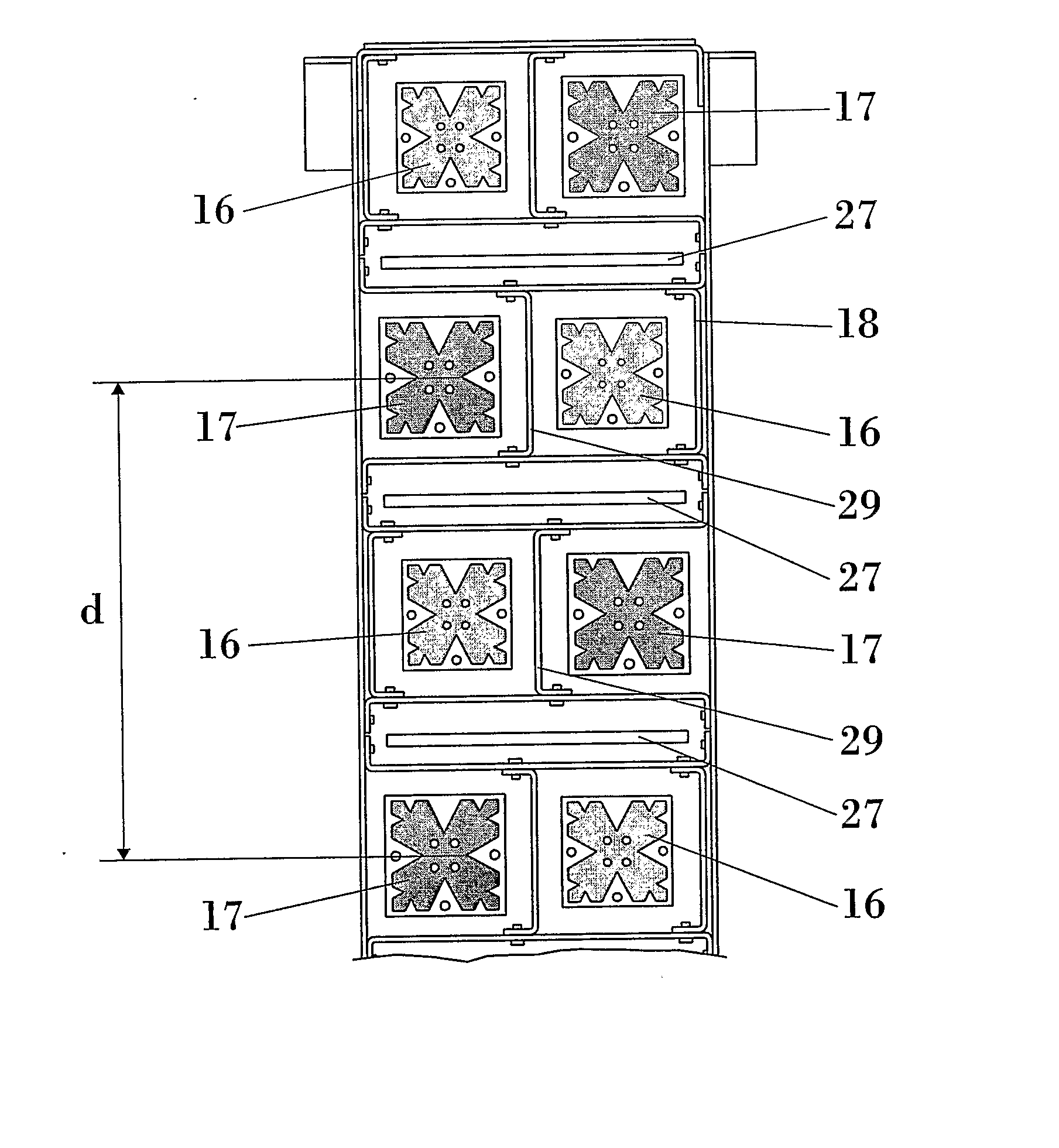
[0032] The multiband antenna array of the invention comprises a first set of radiating elements (17) operating at a first frequency band and a second set of radiating elements (16) operating at a second frequency band. The radiating elements of this antenna system are smaller than λ / 2 or smaller than λ / 3, being (λ) the longest operating wavelength. FIG. 4 shows a few examples of some possible radiating elements (13) that might be used within the scope of the present invention. The height of the radiating elements (13) with respect to the ground plane of the antenna is also small, helping the integration of three dual band antennas on a slim cylinder. Such a height (13) is smaller than 0.15 wavelengths (0.15λ) at the frequency of operation, but also smaller than 0.08λ in several embodiments. Such reduced height is possible because of the feeding technique used to feed the elements. In some embodiments, the radiating elements (13) placed on substrate (15) are fed in four points (14) a...


PUM


Abstract

This invention is in the field of base station antennas for wireless communications. The present invention refers to a slim multi-band antenna array for cellular base stations, which provides a reduced width of the base station antenna and minimizes the environmental and visual impact of a network of cellular base station antennas, in particular in mobile telephony and wireless service networks. A multiband antenna array comprises a first set of radiating elements operating at a first frequency band and a second set of radiating elements operating at a second frequency band, said radiating elements being smaller than λ / 2 or smaller than λ / 3, being (λ) the longest operating wavelength. The ratio between the largest and the smaller of said frequency bands is smaller than 2.

Description

OBJECT OF THE INVENTION [0001] The present invention refers to a slim multi-band antenna array for cellular base stations, which provides a reduced width of the base station antenna and minimizes the environmental and visual impact of a network of cellular base station antennas, in particular in mobile telephony and wireless service networks. The invention relates to a generation of slim base station sites that are able to integrate multiple mobile / cellular services into a compact radiating system. [0002] A Multi Band antenna array of the invention comprises an interlaced arrangement of small radiating elements to significantly reduce the size of the antenna. More specifically the width of this antenna being similar to the width of a typical single band antenna so about half of the width of typical Dual Band antenna. BACKGROUND OF THE INVENTION [0003] The UMTS, third generation of wireless communications systems, that is being added to 2nd generation of wireless communications syste...

Claims


Application Information

Patent Timeline
IPC IPC(8): H01Q21/06
CPCH01Q1/246H01Q1/523H01Q5/42H01Q21/205H01Q21/065
Inventor BORAU, CARMEN MARIA BORJAKIRCHHOFER, JAMES DILLIONTEILLET, ANTHONYBALIARDA, CARLES PUENTE
Owner COMMSCOPE TECH LLC
Learn More