Machine tool

a technology of machine tools and rotating stops, applied in the field of machine tools, can solve the problems of increasing the size of the entire machine, and achieve the effect of eliminating the rotating stopper

Inactive Publication Date: 2008-03-20
DMG MORI SEIKI CO LTD
View PDF17 Cites 18 Cited by
  • Summary
  • Abstract
  • Description
  • Claims
  • Application Information

AI Technical Summary

Benefits of technology

[0019] In the embodiment describing the above characteristics, the ram has the polygonal shape, and the faces composing the plural sides of the polygon are the slide faces, and the sliders contacting t

Problems solved by technology

However, in the case of the first turret disposed at the lower portion of the slant face, a space is needed to be ensured at the rear

Method used


Image

  • Machine tool
  • Machine tool
  • Machine tool

Examples


Embodiment Construction

)

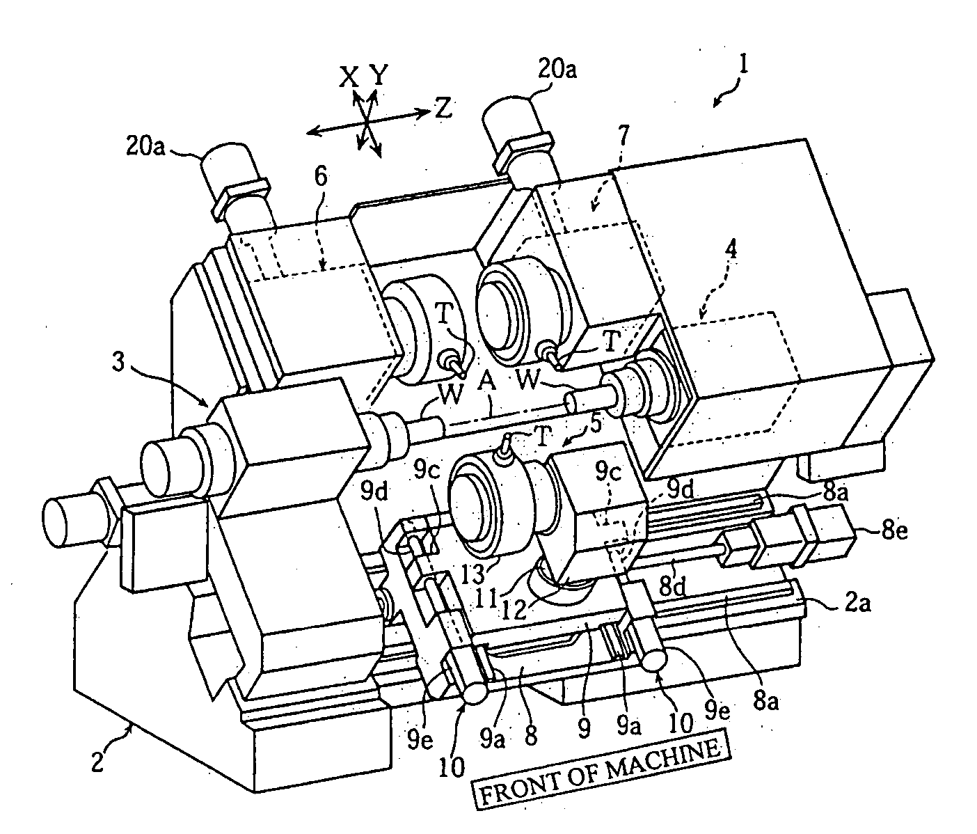
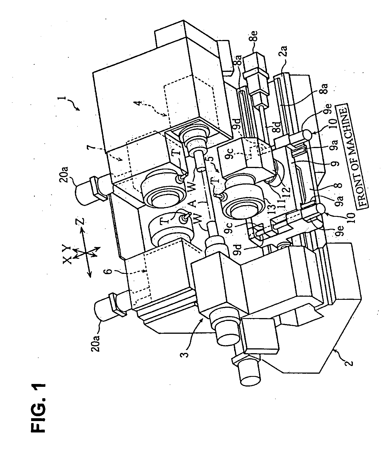
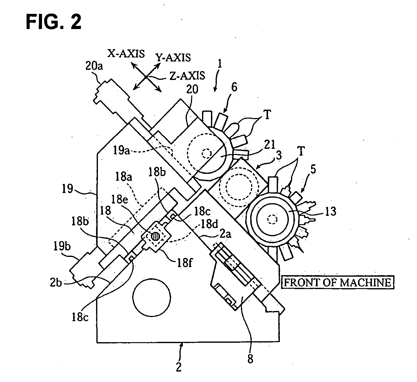
[0028] Hereinafter, embodiments according to the present invention will be described with reference to the attached drawings. FIGS. 1 to 8 are drawings to illustrate a turret lathe according to one embodiment of the present invention.

[0029] In the drawings, “1” denotes a turret lathe according to one embodiment of the present invention, and the turret lathe 1 includes a slant-type bed 2 slanting in a manner that the near side thereof becomes lower when viewed from the front of a machine, a first spindle headstock 3 disposed at the left side portion of the bed 2, a second spindle headstock 4 disposed at the right side portion in a movable manner in the Z-axis direction to be coaxial with the first spindle headstock 3, a first turret 5 disposed at the lower portion positioned at the near side of the bed 2 in a movable manner in the X-axis, Y-axis and Z-axis directions, and second and third turrets 6, 7 disposed at the higher portion positioned at the distant side of the bed 2 in a m...


PUM

PropertyMeasurementUnit
Shapeaaaaaaaaaa

Abstract

A machine tool capable of structuring a turret disposed at a lower portion of a slant face to be movable in the Y-axis direction without causing an increase in the entire machine in size, in which a first turret 5 is structured to include a base member 8 disposed on a bed 2 in a movable manner in a Z-axis direction, a slide base 9 disposed on the base member 8 in a movable manner in an X-axis direction, a pair of X-axis feed mechanisms 10, 10 moving the slide base 9 in the X-axis direction, a ram 11 disposed at a portion of the slide base 9 and between the pair of X-axis feed mechanisms 10, 10 in a movable manner in a Y-axis direction being orthogonal to a plane including the X-axis and Z-axis, and a turret body 12 and a turret head 13 mounted on the ram 11, is provided.

Description

BACKGROUND OF THE INVENTION [0001] 1. Field of the Invention [0002] The present invention relates to a machine tool equipped with a spindle headstock gripping and rotating a workpiece and a turret having many tools radially disposed thereto on a bed thereof. [0003] 2. Description of the Related Art [0004] As a conventional machine tool provided with a turret, there is one including a slant-type bed having a slant face slanting in a manner that a near side thereof becomes lower when viewed from a front side of the machine, a spindle headstock disposed at one side portion of the bed, a first turret disposed at a lower portion positioned at a near side of the slant face, and a second turret disposed at a higher portion positioned at a distant side of the slant face. [0005] [Patent document 1] EP Patent No. 0538515B1 [0006] In the above-described machine tool provided with the slant-type bed, it is possible to structure the turret to be movable in the Y-axis direction being orthogonal t...

Claims


Application Information

Patent Timeline
IPC IPC(8): B23B3/18
CPCB23B3/168B23B29/323B23Q1/015Y10T82/2508B23Q2039/004Y10T29/5153B23Q39/026
Inventor YAMANE, MASAHIROISHIGURO, HARUKI
Owner DMG MORI SEIKI CO LTD
Why Eureka
Try Eureka