Grinding machine spindle end mechanism

A spindle and grinding machine technology, which is applied to the parts of grinding machine tools, grinding/polishing equipment, metal processing equipment, etc., can solve the problems of low work efficiency, cumbersome operation, and potential safety hazards, so as to reduce splash and improve the working environment Effect

Inactive Publication Date: 2008-09-24
PACIFIC TEXTILE MACHINERY CHANGSHU CO LTD
View PDF0 Cites 6 Cited by
  • Summary
  • Abstract
  • Description
  • Claims
  • Application Information

AI Technical Summary

Problems solved by technology

The problem existing in the actual use of the above-mentioned grinding machine spindle head mechanism is: the locking of the taper sleeve 2 and the cone 11 is only achieved by the screwing of the lock nut 4 and the threaded section 111, and the locking is not reliable, and there is a potential safety hazard; secondly , the rotation of the lock nut 4 and the threaded section 111 is divided into left-handed and right-handed. In order to prevent the loosening between the two and the loosening of the grinding wheel 5, the rotation direction of the main shaft 1 must be kept in line with the The screwing directions of the lock nut 4 and the threaded section 111 are consistent. Therefore, the main shaft 1 of the main shaft end mechanism of this structure can only rotate in one d

Method used


Image

  • Grinding machine spindle end mechanism
  • Grinding machine spindle end mechanism
  • Grinding machine spindle end mechanism

Examples


Embodiment Construction

[0012] Through the applicant's description of the embodiments, it will be more helpful to understand the present invention, and make the positive effects of the present invention more manifest, but the embodiments should not be regarded as limiting the solution of the present invention.

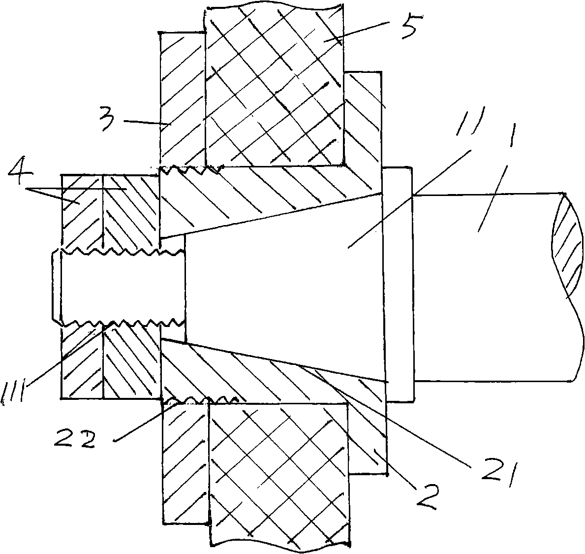
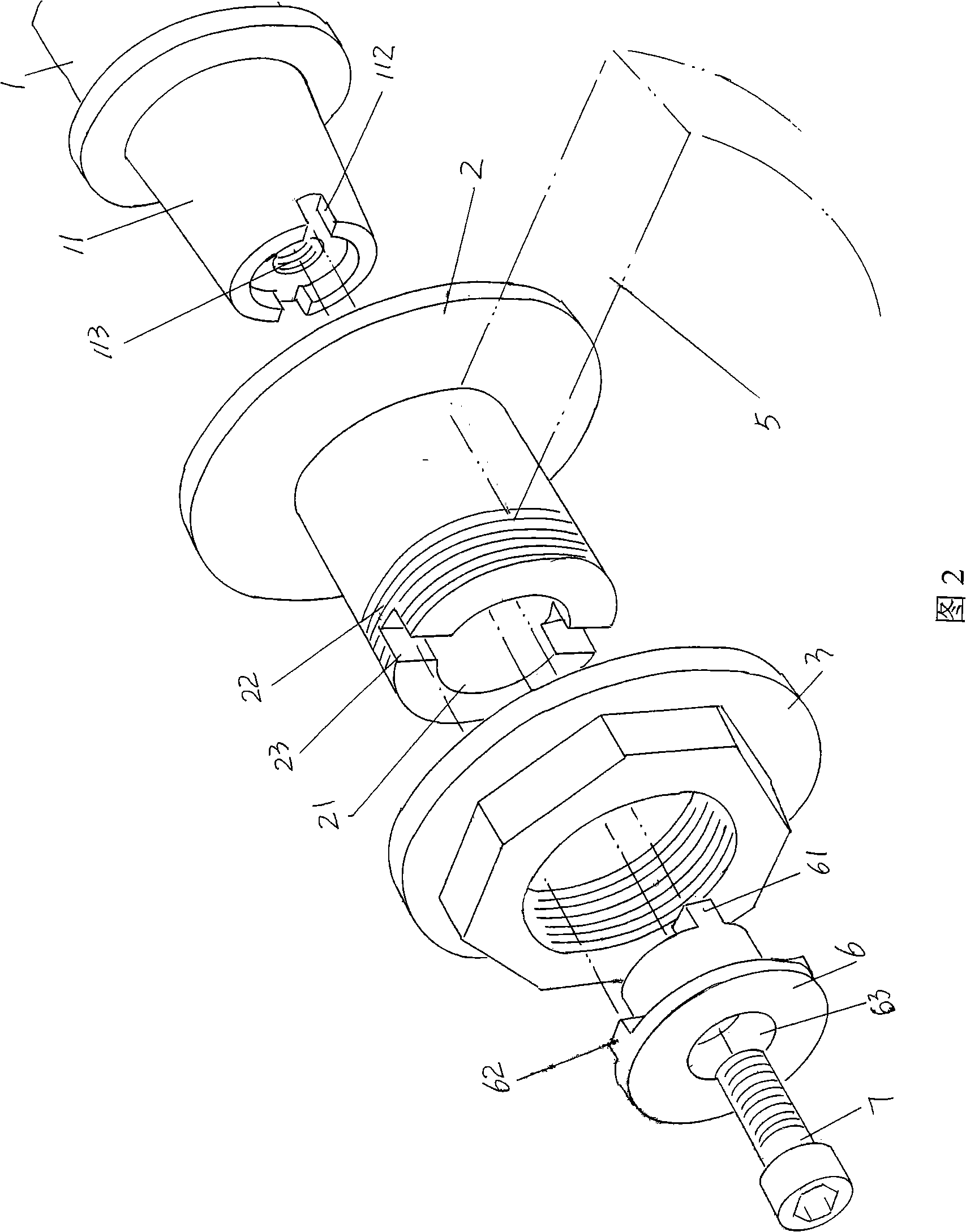
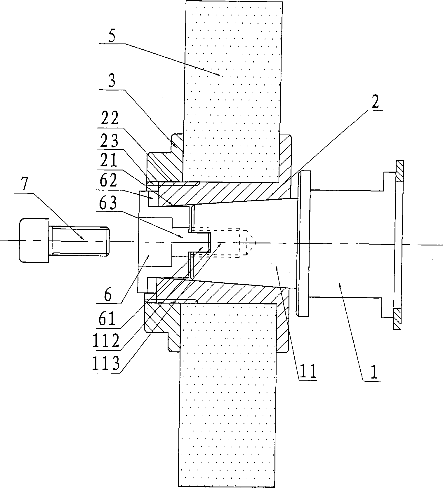
[0013] See Figure 2 and combine image 3 The spindle end mechanism of the grinding machine of the present invention includes a cone 11 arranged at the end of the spindle 1, a taper sleeve 2 with a tapered hole 21 in the middle and a thread 22 on the outer circumference, a compression nut 3, and a set plate 6 and a screw 7, the cone 11 of the main shaft 1 is provided with a square shaft keyway 112 in the radial direction of the left end surface, and a screw hole 113 is processed inwardly in the middle of the left end surface; the taper sleeve 2 is provided in the radial direction of the left end surface A square sleeve keyway 23 is provided, and a grinding wheel 5 is set on the outer circumfer...


PUM


Abstract

The invention relates to a main shaft end apparatus of a grinding machine, which belongs to the technical field of a machining device. The apparatus comprises a taper body arranged at a main shaft end, a taper sleeve which is used for arranging a grinding wheel and provided with a taper hole in the middle and a screw tooth on the external circumference, and a compression nut. The main shaft end apparatus of the grinding machine is characterized in that the apparatus also comprises a holding disc and a screw; a screw hole is arranged in the middle of the holding disc; a pair of sleeve keys is arranged on the inner end face of the holding disc; a pair of shaft keys is arranged on the outer end face of the holding disc; correspondingly, sleeve key grooves used for the sleeve keys to be inserted are arranged on the outer end face at one side of the holding disc facing to the taper sleeve, and shaft key grooves used for the shaft keys to be inserted are arranged on the outer end face at one side of the holding disc facing to the taper body; after passing through the screw hole in the middle of the holding disc, and the screw is rotationally fixed with the screw hole arranged at the center of the taper hole. The main shaft end apparatus of the grinding machine has the advantages that the grinding wheel on the taper sleeve is ensured to be always in a compressed state, the splashing of abrasive particle is reduced through changing the rotation direction of the main shaft when complex workpieces are processed, thereby improving the working condition.

Description

technical field [0001] The invention relates to a grinder spindle end mechanism, which is an improvement on the existing grinder spindle end mechanism, and belongs to the technical field of machining devices. Background technique [0002] Grinding machine main shaft head mechanism in the prior art, its structure is by figure 1 It is disclosed that it includes a cone 11 located at the end of the main shaft 1, a tapered sleeve 2 with a tapered hole 21 in the middle and a thread 22 on the outer circumference for installing the grinding wheel 5, a compression nut 3, and a lock Tightening nut 4, the said compression nut 3 is screwed with the thread 22 on the outer circumference of the taper sleeve 2 to fix the grinding wheel 5 on the taper sleeve 2, and the taper sleeve 2 is sleeved through the taper hole 21 in the middle On the cone 11 at the end of the main shaft 1, the cone 11 is provided with a threaded section 111 in the middle of the front end, and a lock nut 4 is screwed ...

Claims


Application Information

Patent Timeline
IPC IPC(8): B24B41/04
Inventor 卫美红徐群芳
Owner PACIFIC TEXTILE MACHINERY CHANGSHU CO LTD
Why Eureka
Try Eureka