Tool Holding Apparatus

a technology of holding apparatus and tools, which is applied in the direction of mechanical apparatus, manufacturing tools, chucks, etc., can solve the problems of overpowering the holding frictional force, undue load on the spindle of the milling machine, and the strength of the collet clamping cutting tool may become unduly compromised, so as to achieve more accurate and precise milling of materials.

Inactive Publication Date: 2018-05-24
BERG CHARLES MICHAEL
View PDF15 Cites 8 Cited by
  • Summary
  • Abstract
  • Description
  • Claims
  • Application Information

AI Technical Summary

Benefits of technology

[0013]In order to overcome the numerous drawbacks apparent in the prior art, a tool holding apparatus has been devised for use with a machine spindle of the type commonly associated with CNC milling machines, particularly incorporating use of an internal clamping mechanism that effectively eliminates axial rotation and axial pullout of an end mill that can appreciably diminish the precision and accuracy by which the end mill shapes and mills a stock of material.
[0014]It is an object of the present invention to provide a tool holding apparatus that incorporates within its structure centralized and through-wall coolant and lubricant passageways to further effect cooling and lubricating of raw materials undergoing sustained and rigorous milling.
[0015]It is a further object of the present invention to provide a tool holding apparatus that is relatively simple in terms of design and construction and exists as two separable but connected main components for increased accessibility for periodic repair and maintenance while maintaining its overall, inherent concentricity characteristics.
[0016]It is yet another object of the present invention to provide a tool holding apparatus that maintains a high degree of concentricity relatively to the centerline of the machine spindle that is accurate to a level of run out error appropriate to an end mill and the machining process.
[0017]It is a further object of the present invention to provide a tool holding apparatus that does not necessarily depend on the use of expensive externally operated equipment or devices that may pose a threat to the health and safety of the operator.
[0019]In accordance with the present invention a tool holding apparatus has been devised for use with a machine spindle receiver of the type commonly associated with a CNC milling machine, the tool holding apparatus principally comprising a holder nose connected to a holder body having a radially projecting v-flange separating first and second divided sections; the second divided section comprising a geometric arrangement for conforming fitment within the machine spindle receiver; the holder body comprises a centralized axial bore having first, second, and third internal cylindrical sections for housing therewithin an internal assembly comprising a tension bolt, a lock nut, and a thrust nut; the second internal cylindrical section primarily houses a thrust slip washer positioned on a distal side of a lock nut and a stacked arrangement of spring washers on a proximal side of the lock nut; the third internal cylindrical section partially houses the thrust nut having a first outward cylindrical surface geometrically configured with three flat segments that correspond to an equally configured first chamber of the third internal cylindrical section to inhibit rotational motion relatively therewithin, a second outward cylindrical surface configured with a threaded end to threadably engage an internal threaded bore of the holder nose that furthers to seat and retain an end mill under a torque load within an axial bore generally associated with the holder nose, and an inner threaded bore that threadably receives a threaded end section of the tension bolt that upon its rotation in a clockwise manner draws inwardly the position of the holder nose relatively towards the holder body and concentrically aligns and tightly secures the holder nose sufficiently to the holder body; the axial bore comprises a reverse-tapered configuration formed by the progressive change in diameter between rearward and forward ends thereof and three flat sectors integrated within the tapered configuration; and the end mill comprises a cutter end section integrally connecting to a shaft portion configured with a reverse-tapered profile and three flat trigonal sectors each being equally spaced apart from one another about an outer peripheral surface of the reverse-tapered profile to form an overall trigonal tapered configuration sufficiently suited to fit within the equally configured axial bore, collectively surmounting to inhibit axial rotation and axial pullout of the end mill relatively from the holder nose for more accurate and precise milling of materials.

Problems solved by technology

However, in some cases, the milling machine spindle may unduly experience an increased load that can perhaps overwhelm the holding frictional force.
Although the collet nut and associated tapers of the collet and collet chuck portion of the tool holder may adequately compress and clamp the cutting tool's shank within the collet body, the strength with which the collet clamps the cutting tool may become unduly compromised by the applied rotational force and rotational resistance that may be realized when the cutting tool engagingly shears the work piece during milling operations.
Since the respective shapes of the cutting tool's shank and the inner portion of the collet body of the tool holder are inherently cylindrical by design, there is an appreciable tendency for rotational slip of the cutting tool relatively within the tool holder, particularly under a condition of high operating torque for a sustained period of time during rigorous milling operations.
Consequently, unwanted rotational interaction of this kind can adversely cause axial pullout of the cutting tool from the tool holder, leading to possible damage to the tool holder, machine spindle, cutting tool, and / or work piece, and / or further an unbalanced tool holder, resulting in unwanted vibrations that can create chatter and ultimately diminish the surface finish of the work piece and the life of the cutting tool.
Although the usage of a tool holder incorporating a collet may be satisfactory in some regards, particularly where variability thereof is required to accommodate the variety of cutting tools being offered by and used in the industry, industry has come to recognize other forms of tool holders that sufficiently overcome the deficiencies associated with collets, but perhaps compromising in areas of versatility of use and expense.
Although a relative degree of concentricity is realized with a fulfilling option for tool change out to accommodate a variety of cutting tool diameters, possibly to the likes of the collet arrangement, there continues to be an undesirable opportunity for axial slip and pullout of the cutting tool.
Although a shrink-fit tool holder provides a simple yet highly accurate and repeatable grip on the cutting tool, it generally suffers in the area of versatility given that the cutting tool is generally dedicated to the tool holder unless provisions are made to purchase, operate and maintain a heat-shrink machine that can accommodate periodic change out of the cutting tool, which can be a time consuming and costly and expensive option in the long term.

Method used


Image

  • Tool Holding Apparatus
  • Tool Holding Apparatus
  • Tool Holding Apparatus

Examples


Embodiment Construction

[0087]While this invention is susceptible of being embodied in many different forms, the preferred embodiment of the invention is illustrated in the accompanying drawings and described in detail hereinafter with the understanding that the present disclosure purposefully exemplifies the principles of the present invention and is not intended to unduly limit the invention to the embodiments illustrated and presented herein. The present invention has particular utility as a tool holding apparatus to appreciably eliminate rotational slip and axial pullout of an end mill therefrom for more accurate and efficient milling of materials commonly used in the manufacture and fabrication of finished parts and components.

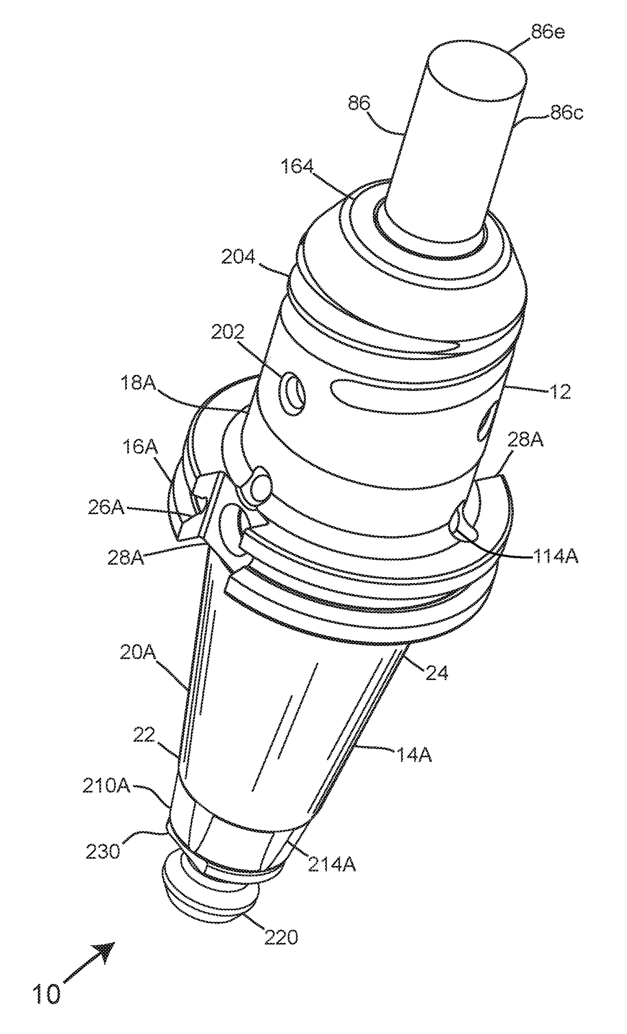
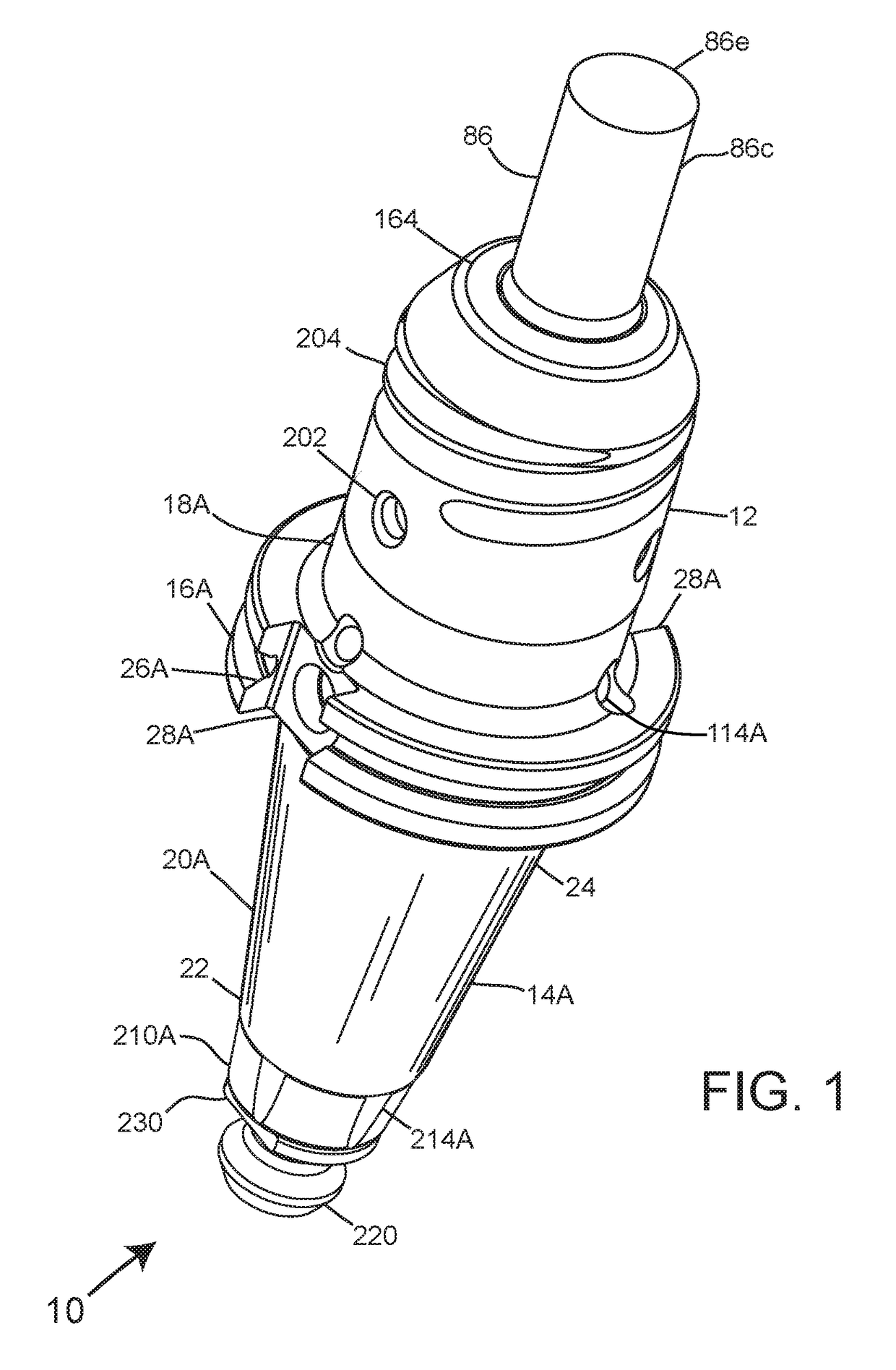
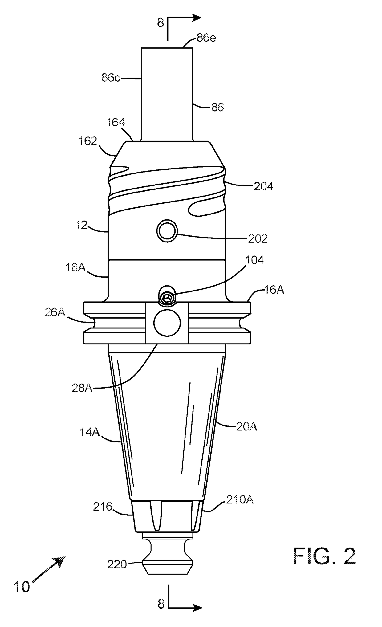
[0088]Referring now to FIGS. 1 and 2, there is shown generally at 10 a tool holding apparatus comprising a holder nose 12 connected to a holder body 14A having a radially projecting v-flange 16A separating a first divided section 18A from a second divided section 20A configured ...


PUM

PropertyMeasurementUnit
hoop stressaaaaaaaaaa

Abstract

A tool holding apparatus for interfacing a machine spindle receiver of a milling machine, which includes a holder nose connected to a holder body configured with a first divided section integrally connecting to a second divided section and a centralized axial bore for housing therewithin a tension bolt, a lock nut, and a thrust nut. The holder nose includes an axial bore incorporating a reverse-tapered configuration and three flat sectors to correspond with an equally configured shaft portion of a tool, whereupon the threaded attachment of the thrust nut to the holder nose furthers a locking arrangement of the tool within the axial bore to prevent inadvertent axial and rotational movement thereof during aggressive milling operations.

Description

FIELD OF THE INVENTION[0001]The present invention is generally directed to a tool holding apparatus for use with and placement within a machine spindle commonly associated with a CNC milling machine. More specifically, the tool holding apparatus relates to an improvement of a tool clamping mechanism that appreciably eliminates axial rotation and axial pullout of an end mill that can adversely diminish the precision by which the end mill shapes and mills a stock of material.BACKGROUND OF THE INVENTION[0002]Computer numerical controlled or CNC machines are sophisticated metalworking tools that can generate intricate parts required by modern day technology. The CNC term refers to a large group of machines that utilize computer logic to control movements of a cutting head or spindle or even the work piece itself to fulfill the metalworking task. CNC machines may commonly include milling machines, lathes, and grinders.[0003]Milling machines, for example, automatically cut materials, incl...

Claims


Application Information

Patent Timeline
Patent Type & Authority Applications(United States)
IPC IPC(8): B23B31/117
CPCB23B31/117B23B2250/12B23B2231/24B23B31/005B23B31/11B23B2231/0256Y10T409/30952Y10T279/17111Y10T409/304032B23Q11/1023B23C5/26
Inventor BERG, CHARLES MICHAEL
Owner BERG CHARLES MICHAEL
Why Eureka
Try Eureka