
Bonnet for Automobile

Inactive Publication Date: 2008-03-20
TORAY IND INC
View PDF27 Cites 18 Cited by
  • Summary
  • Abstract
  • Description
  • Claims
  • Application Information

AI Technical Summary

Benefits of technology

[0009] In such an FRP bonnet for an automobile, since a function as a structural member required with a necessary rigidity is given to the FRP outer member while the entire bonnet is maintained light, even if the FRP inner member is formed as a divided structure, it becomes possible to satisfy the rigidity and function required for the entire bonnet for an automobile. Namely, this divided structure of the inner member can be said to be a structure capable of being employed peculiarly to an FRP bonnet, and usually this structure is not employed for a metal bonnet because, if such an inner divided structure is employed, the number of inner member forming processes (for example, press forming processes) increases and the efficiency reduces as compared with a case where an integral product is formed in a single process. In a case of FRP, however, as long as molds for the respective divided inner parts are prepared, it becomes possible to employ the inner divided structure without particularly reducing the efficiency.
[0047] Furthermore, because an energy absorbing performance can be exhibited by the deformation of the inner member having the rotational deformation possible sectional portion itself, the energy absorbing performance of the whole of the bonnet may be further increased.

Problems solved by technology

By the way, although recently FRP bonnets for automobiles have been developed for a first purpose of lightening and various structures are proposed aiming mainly to increase the strength and the rigidity of a required part (for example, JP-A-2003-146252), there is almost no proposal to form an adequate structure for a bonnet for an automobile, from the viewpoint of satisfying the above-described required performance at the time of collision accident, etc.
When such an inner member with a picture frame-like shape is bonded to an outer member, although the rigidity of the entire FRP bonnet can be maintained high and the amount of deformation thereof can be suppressed small, it becomes difficult to exhibit a desirable impact relaxation performance as aforementioned.
Particularly, when it is tried to achieve a bending deformation of a bonnet at a dogleg-like shape at the time of collision accident, etc., it becomes necessary to provide a constriction and the like, which becomes a trigger of the bending deformation at a dogleg-like shape, to the inner member with a picture frame-like shape, the configuration of the entire inner member becomes complicated, and the difficulty on molding increases.
Further, in the inner member with a picture frame-like shape as described above, at the time of molding the inner member, a large-sized mold having substantially the same size as that for an outer member is required, the scale of equipment becomes large, and the cost for production and the difficulty on the production increase.
In a case of FRP, however, as long as molds for the respective divided inner parts are prepared, it becomes possible to employ the inner divided structure without particularly reducing the efficiency.
However, the reinforcing fibers in the FRP bonnet for an automobile are not particularly limited, it is also possible to use other reinforcing fibers or to use carbon fibers together with the other reinforcing fibers.
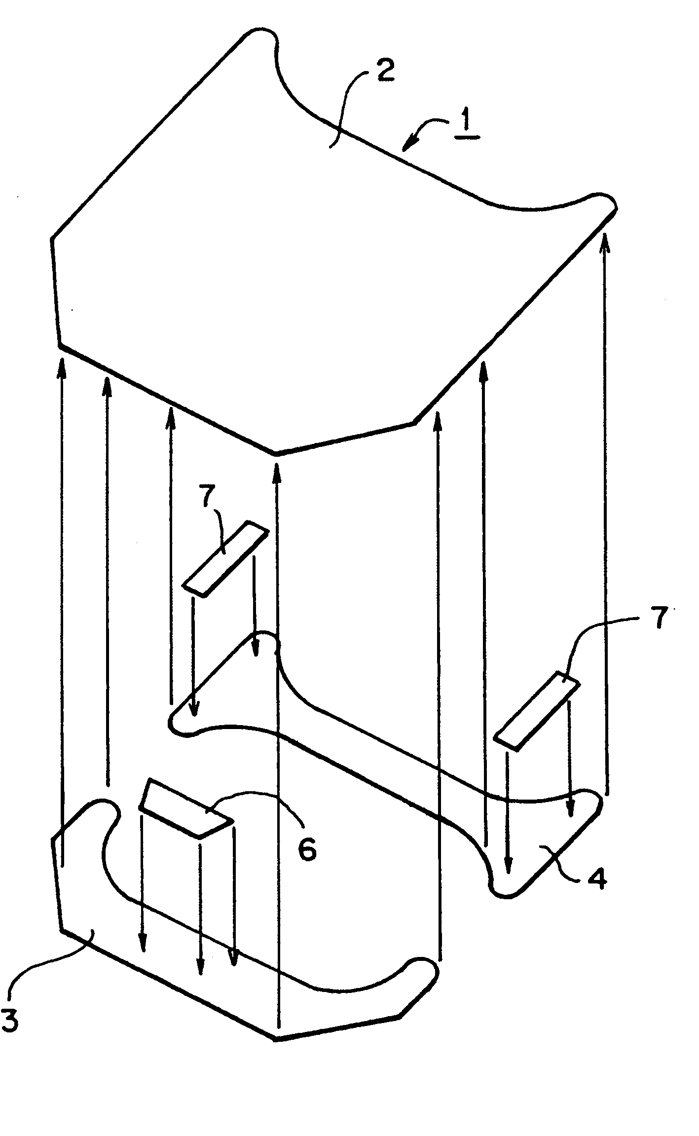
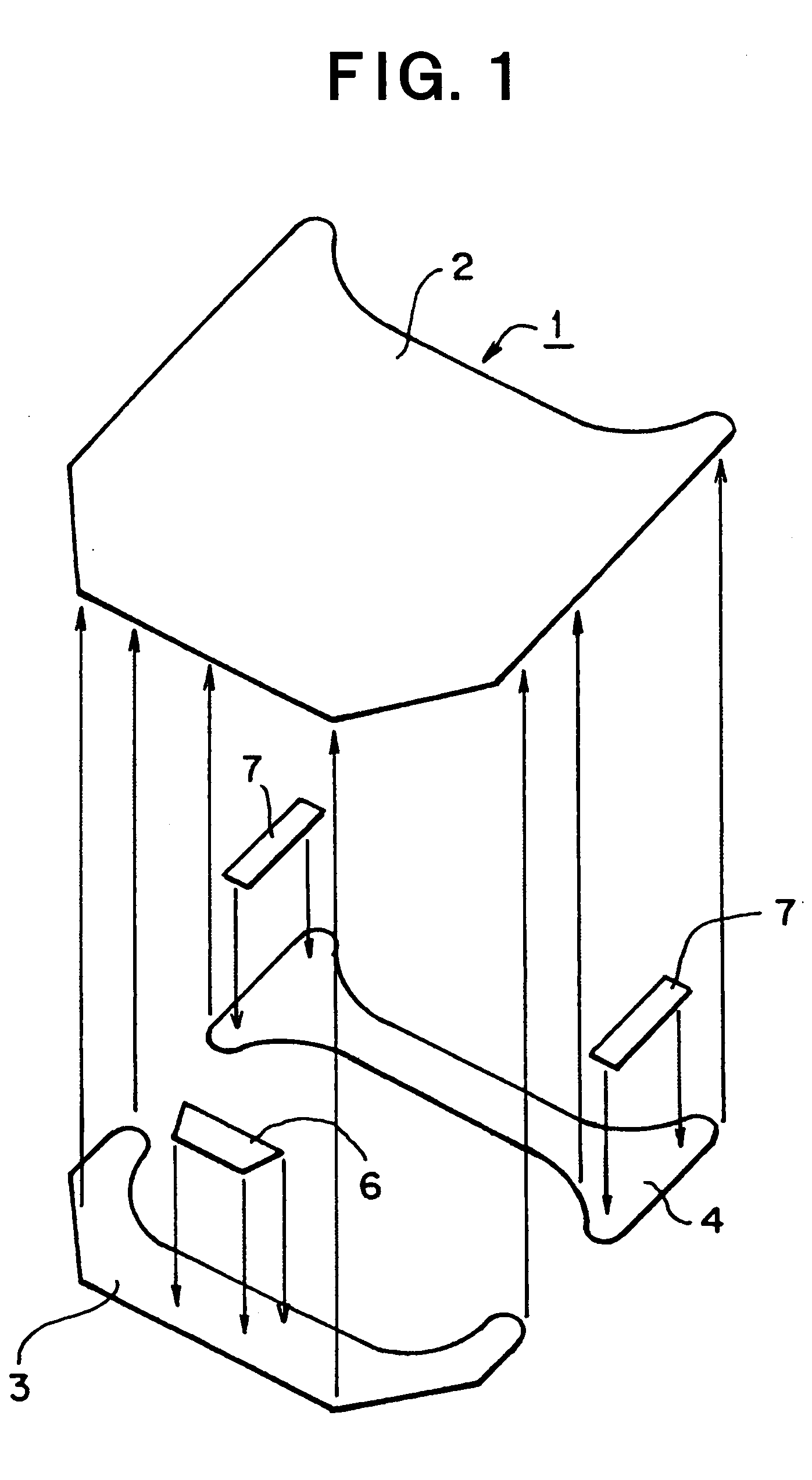
Further, in a case of an FRP bonnet having a light and high-rigidity outer member, an inner member joined to the outer member (including an inner member divided into two parts in a forward and backward direction of a vehicle body) is frequently disposed along an outer edge of the outer member and frequently is not disposed in a central portion, and in such a case, the device on the shape of inner member cannot be applied in the central portion of the bonnet.
In particular, in a case of an outer member formed from a carbon fiber reinforced plastic (CFRP) as aforementioned, because of its high rigidity, the whole of the bonnet moves vertically while a certain shape thereof is maintained as it is, and therefore, the energy absorbing performance is rapidly damaged when the inner member disposed along the outer edge of the outer member comes into contact with the vehicle body or a mounted inside material, and the damage to a pedestrian may become great.

Method used


Image

  • Bonnet for Automobile
  • Bonnet for Automobile
  • Bonnet for Automobile

Examples


Embodiment Construction

[0085] Hereinafter, desirable embodiments will be explained referring to the figures:

[0086]FIG. 1 shows a bonnet for an automobile according to one embodiment. In FIG. 1, symbol 1 shows the whole of the bonnet for an automobile, and the bonnet 1 comprises an FRP outer member 2 positioned at a surface side, and FRP front inner member 3 and rear inner member 4 which are joined to the back surface side of the outer member and separated into two parts in a forward and backward direction of a vehicle body. FRP outer member 2 is spread in a plane direction over the entire surface of the bonnet, and formed as a curved shape required depending upon the kind of automobile. This outer member 2 may be formed as an FRP single plate structure, or may be formed as a sandwich structure in which a core material (for example, a core material formed from a foamed material) is interposed between FRP skin plates. Although it is possible to form front inner member 3 and rear inner member 4 as sandwich ...


PUM


Abstract

A bonnet for an automobile, the bonnet having an outer made from FRP and an inner made from FRP, joined to the back-surface side of the outer, wherein the inner is separated into two parts in the forward and backward direction of a vehicle body. The bonnet can satisfy impact absorbing performance and predetermined required performance for deformation in a collision accident etc., and can improve easiness of production.

Description

RELATED APPLICATION [0001] This is a §371 of International Application No. PCT / JP2005 / 015646, with an international filing date of Aug. 29, 2005 (WO 2006 / 025315 A1, published Mar. 9, 2006), which is based on Japanese Patent Application No. 2004-252335, filed Aug. 31, 2004.TECHNICAL FIELD [0002] The technology in this disclosure relates to a bonnet for an automobile made from an FRP (fiber reinforced plastic), and specifically, relates to a bonnet for an automobile capable of effectively absorbing an impact load and having an excellent productivity. BACKGROUND ART [0003] Recently, enhancement of safety at a collision accident etc. has been required for an automobile, and in particular, enhancement of performance for protecting a pedestrian at an accident etc. as well as enhancement of safety for a crew side, when an impactive external force is applied, have been required. When an automobile collides with a pedestrian, the pedestrian receives an impact load on the leg or the head agai...

Claims


Application Information

Patent Timeline
IPC IPC(8): B60R21/34B62D25/10B62D29/04
CPCB60R21/34B62D29/043B62D25/105B60R2021/343
Inventor KIMOTO, YUKITANEKIYAMA, HIROSHI
Owner TORAY IND INC
Learn More