Method of machining injection hole in nozzle body, apparatus therefore, and fuel injection nozzle produced using the method and apparatus

Active Publication Date: 2008-03-20
MITSUBISHI HEAVY IND ENGINE & TURBOCHARGER LTD
View PDF8 Cites 14 Cited by
  • Summary
  • Abstract
  • Description
  • Claims
  • Application Information

AI Technical Summary

Benefits of technology

[0033]The fuel injection nozzle claimed in claim 14 has a nozzle body having concave portions of very small depth on its conical seat face, the concave portions being formed to extend along generation lines of the conical seat face by abrasive fluid flowing processing using the apparatus of claim 11.
[0034]The fuel injection nozzle claimed in claim 15 has a nozzle body having concave portions of very small depth formed on its conical seat face by abrasive fluid flowing process

Problems solved by technology

One of important problems to be solved in processing of rounding the entrance corners is to even fuel injection characteristic of each of the injection holes.
And there has been problems that such variations can not be eliminated by abrasive fluid flowing processing and fuel injection characteristic of each injection hole is not evened.
When fuel injection characteristic of each of the injection hole is not even, local high temperature zones and fuel rich zones occur in the combustion chamber of the engine resulting in decreased combustion efficiency and deteriorated exhaust emission.
As a result, unexpected separation of fuel flow may occur near the needle valve and injection holes in actual operation of engines, occurrence of cavitation erosion is induced, resulting in occurrence of breakage failure in the injection nozzle and uneven fuel injection characteristic.
However, the flow passage of abrasive fluid is different from the actual flow passage of fuel when fuel is injected in actual operation of eng

Method used


Image

  • Method of machining injection hole in nozzle body, apparatus therefore, and fuel injection nozzle produced using the method and apparatus
  • Method of machining injection hole in nozzle body, apparatus therefore, and fuel injection nozzle produced using the method and apparatus
  • Method of machining injection hole in nozzle body, apparatus therefore, and fuel injection nozzle produced using the method and apparatus

Examples


first embodiment

The First Embodiment

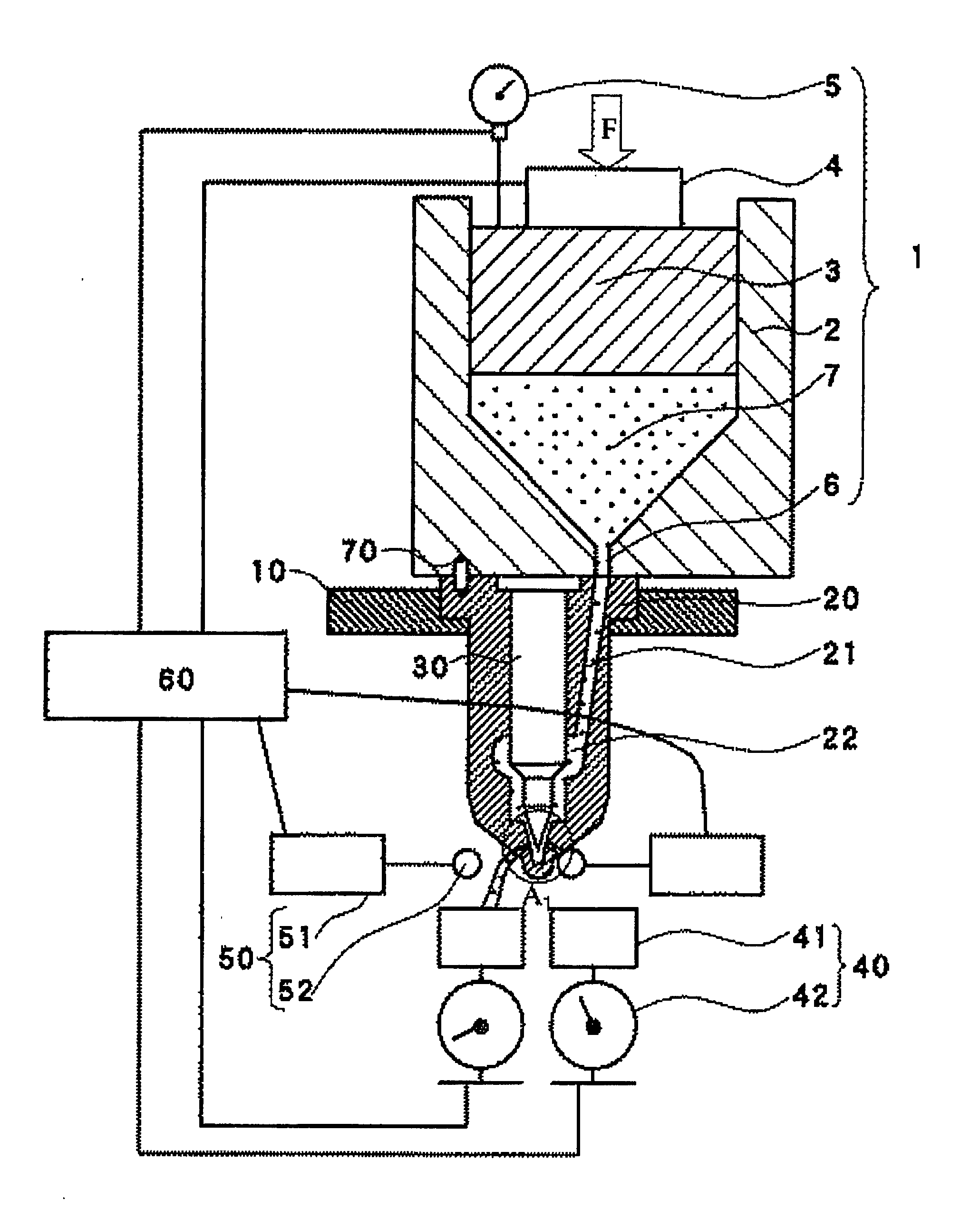
[0044]First, the first embodiment of the invention will be explained referring to FIGS. 1 to 4. FIG. 1 is a schematic representation of an apparatus for machining injection holes of a nozzle body in the first embodiments.

[0045]The apparatus comprised mainly of an abrasive fluid supply section 1, a mounting platform 10, a nozzle body 20 to be processed, an insert tool 30 for abrasive fluid flowing processing, processing end detection sections 40, flow blocking sections 50, and a controller 60.

[0046]The abrasive fluid supply section 1 is composed of a barrel 2, a piston 3, a load detector 4, a displacement detector 5, and a piston drive device not shown in the drawing. The barrel 2 has an inside space in which abrasive fluid 7 is contained. A passage 6 for the abrasive fluid to flow through that has a diameter approximately as same as a diameter of fuel passage 21 of the nozzle body to be processed, is provided at the lower end of the inside space of the barrel 2. ...

second embodiment

The Second Embodiment

[0065]Next, the second embodiment will be explained. In this embodiment, procedure in abrasion fluid processing in the second embodiment is the same as that in the first embodiment, an insert tool 30 different in shape from the insert tool 30 in the first embodiment is used in the second embodiment, because the insert tool in the second embodiment must be fixed in rotation position relative to the nozzle body. The injection hole processing apparatus shown in FIG. 1 can be used for performing the second embodiment of the abrasion fluid processing.

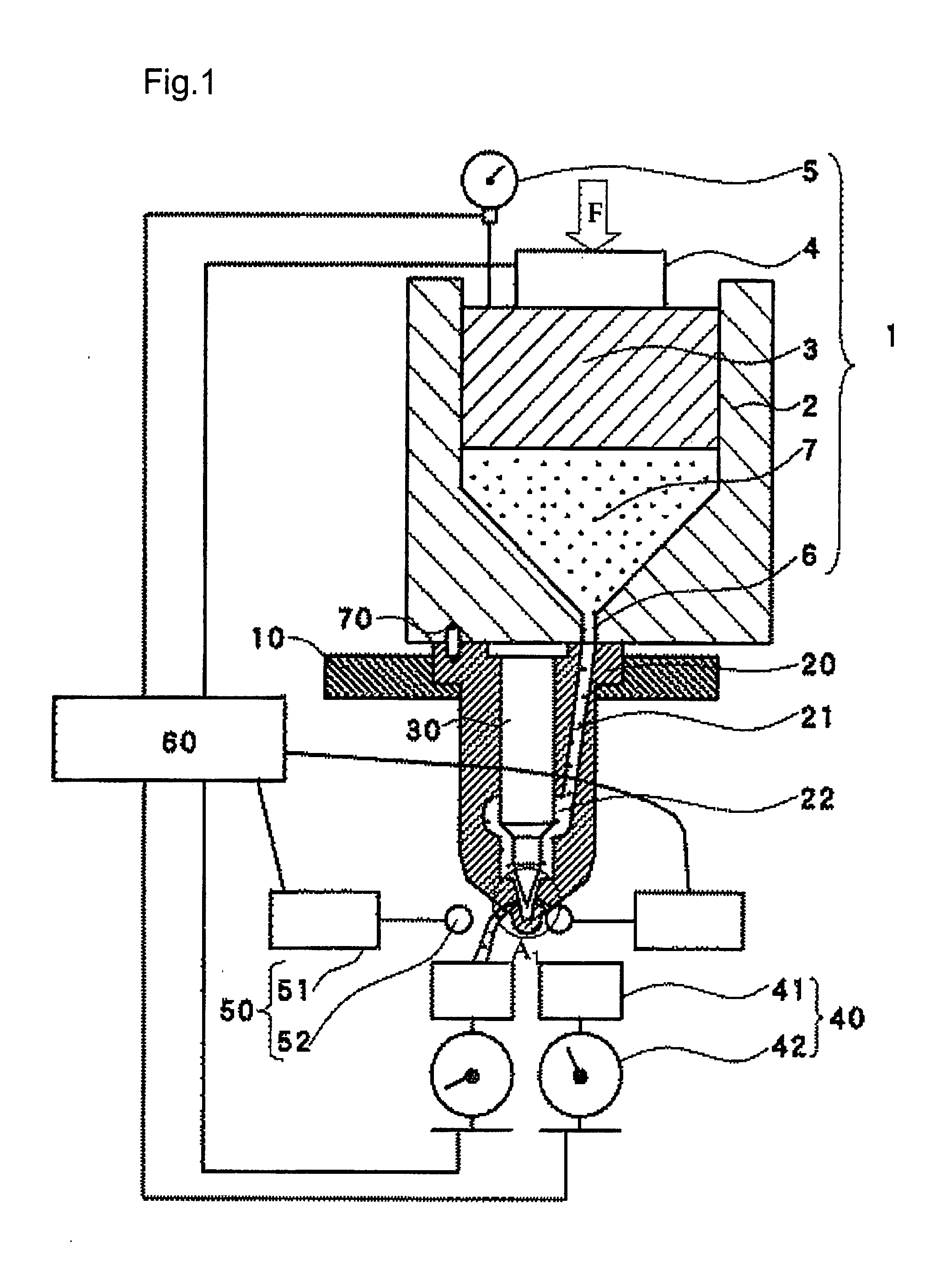
[0066]FIG. 5a is a view showing the shape of the forefront part of the insert tool used in the second embodiment, FIG. 5b is an enlarged sectional view of a part A1 in FIG. 1 near injection holes, and FIG. 5c is a section along line B3-B3 in FIG. 5b.

[0067]As shown in FIG. 5a, the insert tool 30 used in the embodiment has a conical end part to be seated on the conical seat face 23 in the nozzle body, and a plurality of p...

third embodiment

The Third Embodiment

[0074]Next, the third embodiment will be explained. This embodiment differs from the first and second embodiments in that the insert tool is differently shaped and that abrasive fluid flowing processing of one injection hole is performed at a time.

[0075]FIG. 6 is a schematic representation of an apparatus for machining injection holes of a nozzle body in the third embodiment. FIG. 7a is a view showing the shape of the forefront part of the insert tool used in the third embodiment, FIG. 7b is an enlarged sectional view of a part A2 in FIG. 6 near injection holes when sectioned by a plane containing the central axis of an injection hole and the central axis of the insert tool, FIG. 7c is a section along line B4-B4 in FIG. 7b, and FIG. 7d is a sectional view when sectioned by a containing the center line of the straight part of a passage groove and the central axis of the insert tool (section along line B5-B5 in FIG. 7c)

[0076]As shown in FIG. 7a, the insert tool 30 ...


PUM

PropertyMeasurementUnit
Pressureaaaaaaaaaa
Flow rateaaaaaaaaaa
Radiusaaaaaaaaaa

Abstract

The object of the invention is to provide a fuel injection nozzle with which occurrence of cavitation erosion due to occurrence of separation of fuel flow near the needle valve and injection holes is suppressed and variation in fuel injection characteristic is reduced, a method of machining injection holes, and an apparatus therefore to attain the object. An insert tool shaped like the needle valve or an insert tool having a conical surface similar to the needle valve and a groove or grooves are on the conical surface to introduce abrasive fluid to the injection holes, is inserted in the central hollow of the nozzle body when performing abrasive fluid flowing processing to round entrance corners of the injection holes, and the processing of each of the injection holes is stopped when flow rate of abrasive fluid flowing out through relevant injection hole reaches a predetermined value.

Description

BACKGROUND OF THE INVENTION[0001]1. Field of the Invention[0002]The present invention relates to a method of machining nozzle holes in a nozzle body composing a fuel injection nozzle for internal combustion engines, an apparatus for machining the nozzle holes, and fuel injection nozzles produced using the method and apparatus.[0003]2. Description of the Related Art[0004]A fuel injection nozzle has been widely used which is composed such that a needle valve is placed for reciprocation in a central hollow of a nozzle body having a plurality of injection holes, and fuel is allowed to be injected through the injection holes provided in the downstream side of the seating position of the needle valve intermittently by allowing the needle valve to be seated on or departs from the seat face. In recent years injection nozzles have been required to improve in fuel atomization in point of view of reduction in fuel consumption, improvement in exhaust gas emission, stability in operation of inte...

Claims


Application Information

Patent Timeline
IPC IPC(8): F02M61/18B05B1/00B24C1/00B24C3/32
CPCF02M61/168F02M61/1806F02M61/1833Y10T29/49432F02M2200/8069F02M2200/8092F02M2200/04
Inventor KANEKO, TAKASHI
Owner MITSUBISHI HEAVY IND ENGINE & TURBOCHARGER LTD
Why Eureka
Try Eureka