Frequency-locked clock generator

a generator and frequency-locked technology, applied in the direction of electrical equipment, pulse automatic control, etc., can solve the problems of affecting the preventing adequate updating of the output clock signal, and jitter performance of the pll, so as to reduce the cost, improve the jitter, and improve the accuracy and stability of the output signal

Active Publication Date: 2008-03-20
AVAGO TECH INT SALES PTE LTD
View PDF1 Cites 26 Cited by
  • Summary
  • Abstract
  • Description
  • Claims
  • Application Information

AI Technical Summary

Benefits of technology

[0006]Accordingly, the present invention is directed to a reduced cost clock generator that produces an accurate and stable output signal having improved jitter and updating performance for large divider ratios.

Problems solved by technology

Consequently, the updating performance of the PLL is impaired when a low frequency reference signal is used to generate a high frequency clock signal.
Specifically, for large divider ratios, the limited loop bandwidth may prevent adequate updating of the output clock signal.
In turn, the jitter performance of the PLL suffers.
Overall, the PLL is an expensive design that provides poor performance in terms of slow response / updating time and jitter control when used to generate a high frequency output clock signal from a low frequency input signal.

Method used


Image

  • Frequency-locked clock generator
  • Frequency-locked clock generator
  • Frequency-locked clock generator

Examples


Embodiment Construction

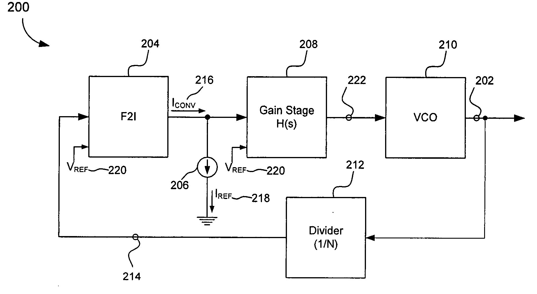
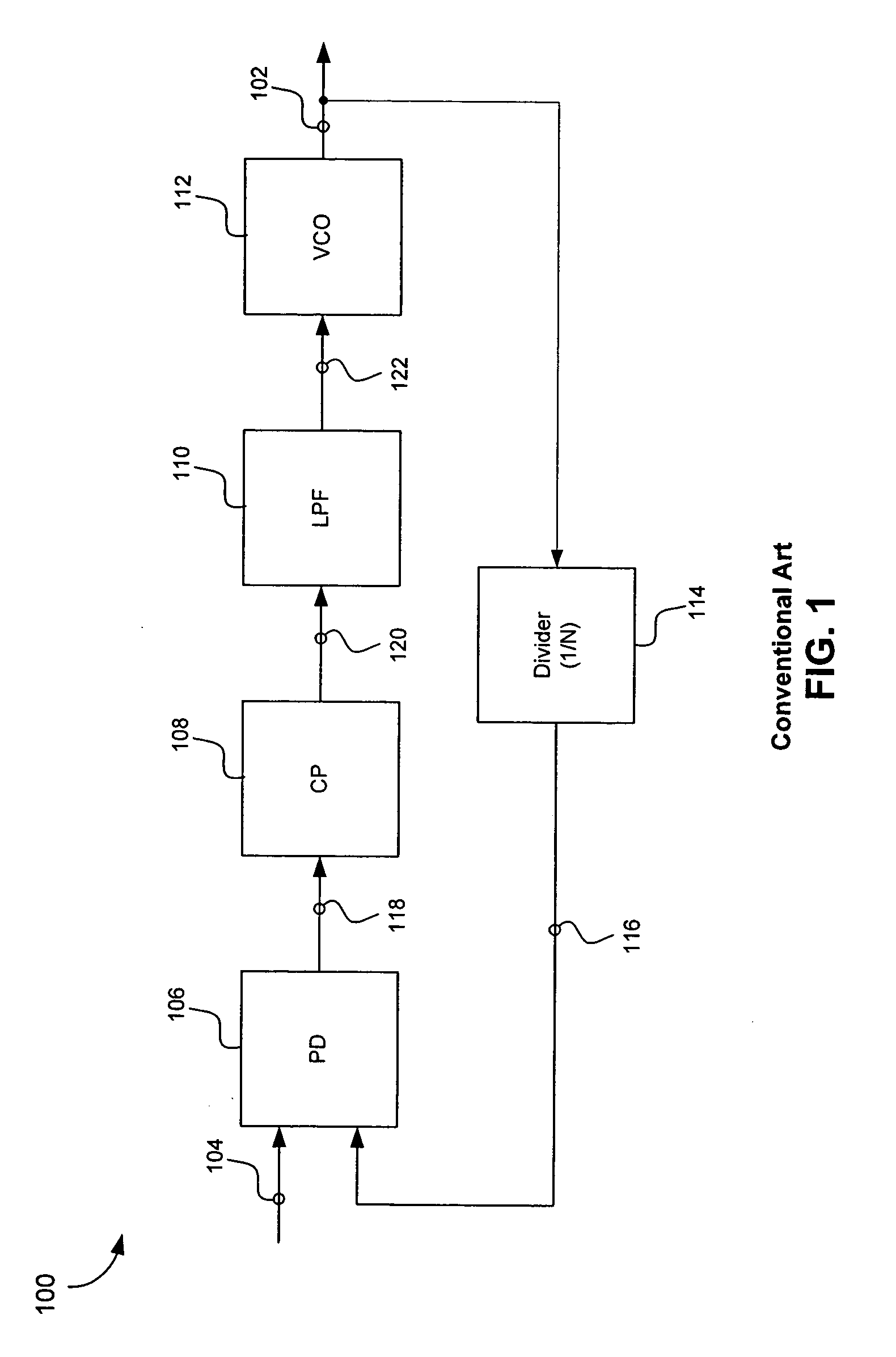
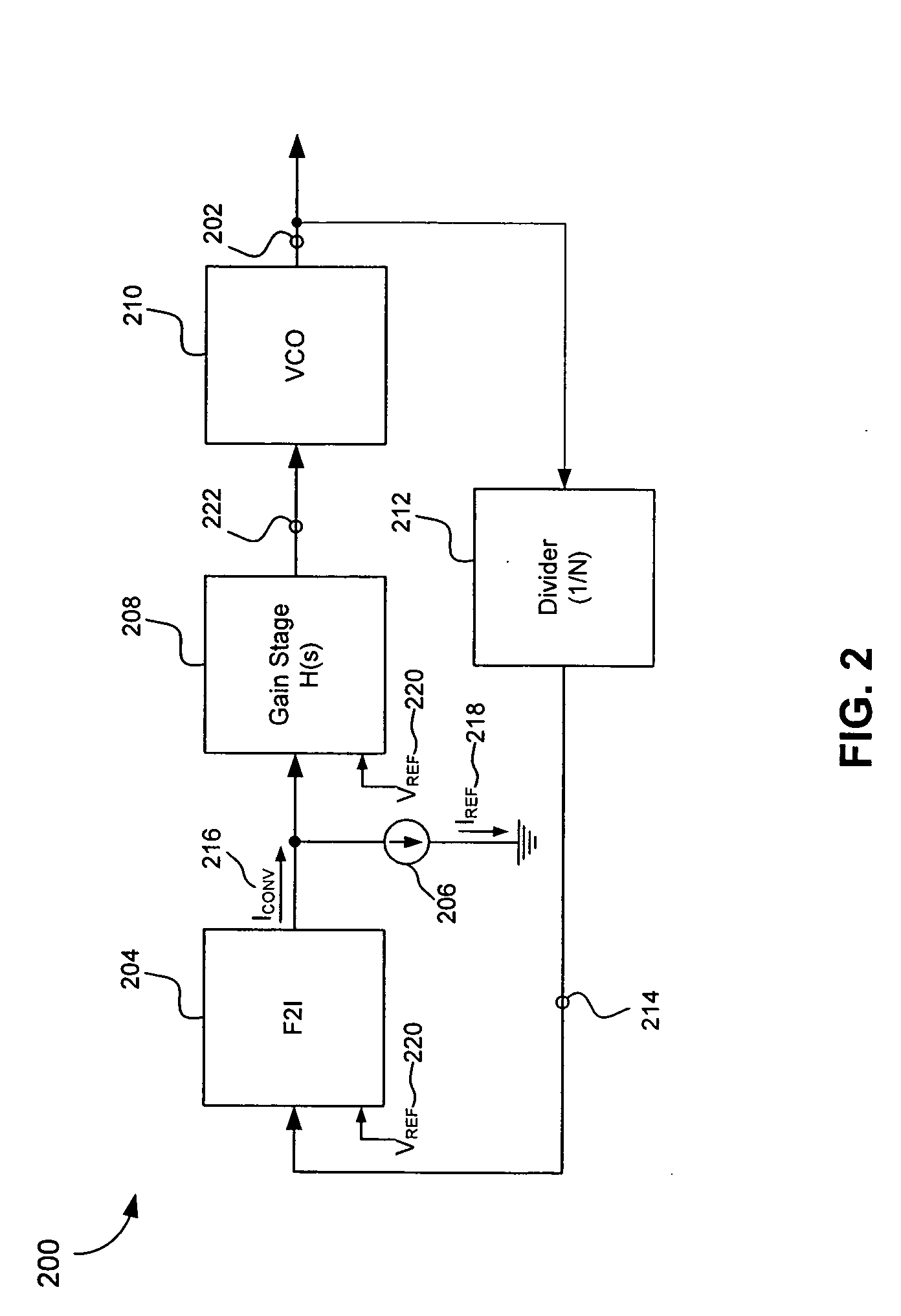
[0018]FIG. 1 illustrates a conventional phase-locked loop (PLL) 100. In general, the conventional PLL 100 is used to generate an output signal 102 having a desired output frequency (i.e., fout) from an input signal 104 having a given reference frequency (i.e., fref). Often, the output signal 102 is a relatively high frequency signal and the input signal 104 is a relatively low frequency signal (i.e., fout>fref). Accordingly, the conventional PLL 100 is used to generate the high frequency output signal 102 from the lower frequency input signal 104. The input signal 104 can be considered a reference clock.

[0019]As shown in FIG. 1, the conventional PLL 100 includes a phase detector (PD) 106, a charge pump (CP) 108, a low pass filter (LPF) 110, a voltage-controlled oscillator 112 and a frequency divider 114. The conventional PLL 100 is arranged as a negative feedback system. An output of the VCO 112 provides the output signal 102. The frequency divider 114 generates a comparison signal ...


PUM


Abstract

A frequency-locked clock generator includes a voltage-controlled oscillator (VCO), a frequency-to-current converter, a reference current source and a gain stage. The VCO generates an output signal. The frequency-to-current converter generates a converter current proportional to a frequency of the output signal. The reference current source generates a reference current. The gain stage generates a control signal based on a difference between the converter current and the reference current. The control signal is applied to the VCO to adjust the frequency of the output signal. Feedback forces the VCO to generate an output clock signal such that the corresponding current it produces (i.e., the converter current) is equal to the reference current. When in lock, the frequency of the output signal is determined by a time constant (or equivalent time constant) of the frequency-locked clock generator.

Description

BACKGROUND OF THE INVENTION[0001]1. Field of the Invention[0002]The present invention generally relates to clock generators. More specifically, the present invention provides a frequency-locked clock generator having improved jitter and updating performance for large divider ratios.[0003]2. Related Art[0004]Often, a phase-locked loop (PLL) is used to generate an output clock signal from a given input signal having a reference frequency. The frequency of the output signal compared to the frequency of the input signal is considered the divider ratio of the PLL. The reference input signal is generally a relatively low frequency signal generated by an expensive crystal oscillator.[0005]The loop bandwidth of the PLL is limited by the frequency of the input reference signal. Consequently, the updating performance of the PLL is impaired when a low frequency reference signal is used to generate a high frequency clock signal. Specifically, for large divider ratios, the limited loop bandwidth...

Claims


Application Information

Patent Timeline
Patent Type & Authority Applications(United States)
IPC IPC(8): H03L7/00
CPCH03L7/02H03L7/00
Inventor KWAN, TOMLI, NING
Owner AVAGO TECH INT SALES PTE LTD
Why Eureka
Try Eureka