

Dual mode AES implementation to support single and multiple AES operations
- Summary
- Abstract
- Description
- Claims
- Application Information
AI Technical Summary
Benefits of technology
Problems solved by technology
Method used
Image

Examples
Embodiment Construction
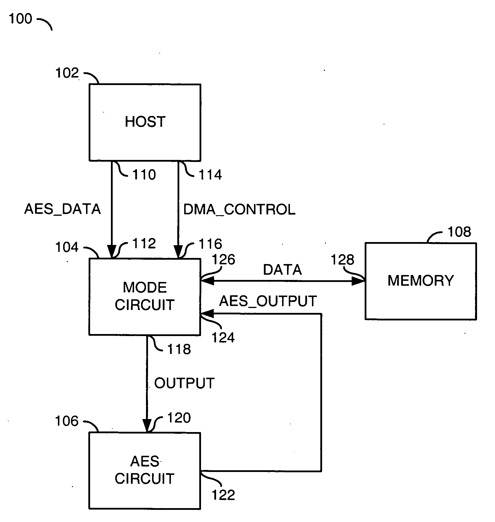
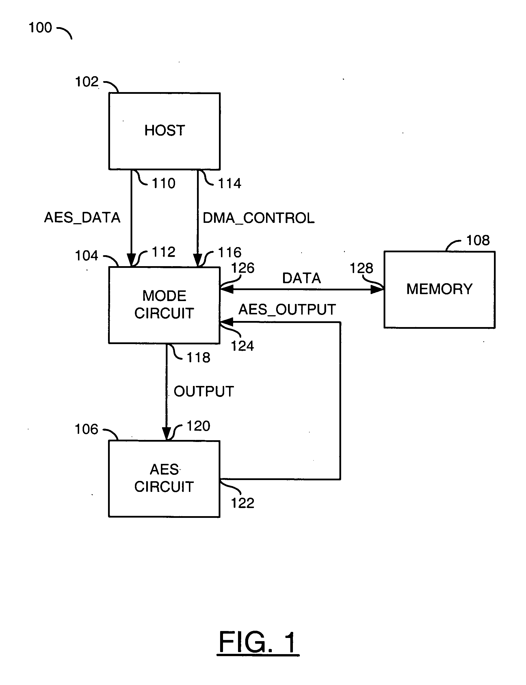
[0013]Referring to FIG. 1, a block diagram of a system 100 is shown in accordance with a preferred embodiment of the present invention. The system 100 generally comprises a block (or circuit) 102, a block (or circuit) 104, a block (or circuit) 106, and a block (or circuit) 108. The circuit 102 may be implemented as a host processor. The circuit 104 may be implemented as a mode circuit. The circuit 106 may be implemented as an AES circuit. The circuit 108 may be implemented as memory. In one example, the memory 108 may be implemented as a SDRAM. The host processor 102 may have an output 110 that may present a signal (e.g., AES_DATA) and an output 114 that may present a signal (e.g., DMA_CONTROL). The mode circuit 104 may have an input 112 that may receive the signal AES_DATA, an input 116 that may receive the signal DMA_CONTROL, an input 124 that may receive a signal (e.g., AES_OUTPUT) and an input / output 126 that may receive / present a signal (e.g., DATA). The mode circuit 104 may ha...
PUM
 Abstract
Description
Claims
Application Information