Ammonia Vapor Storage and Purge System and Method

a technology of ammonia vapor and purge system, applied in the direction of machines/engines, mechanical equipment, separation processes, etc., can solve the problems of oversupply of reductant, insufficient supply of reductant, and exacerbate such problems

Inactive Publication Date: 2008-03-20
FORD GLOBAL TECH LLC
View PDF6 Cites 13 Cited by
  • Summary
  • Abstract
  • Description
  • Claims
  • Application Information

AI Technical Summary

Problems solved by technology

However, the inventors herein have recognized several issues with such a system.
For example, a lack of coordination between vapor reductant and reductant delivered from the tank may result in insufficient reductant supply, or an over-supply of reductant.
Further, uncertainties in the amount of vapors delivered may further exacerbate such issues, especially when vapor delivery is first commenced.

Method used


Image

  • Ammonia Vapor Storage and Purge System and Method
  • Ammonia Vapor Storage and Purge System and Method
  • Ammonia Vapor Storage and Purge System and Method

Examples


Embodiment Construction

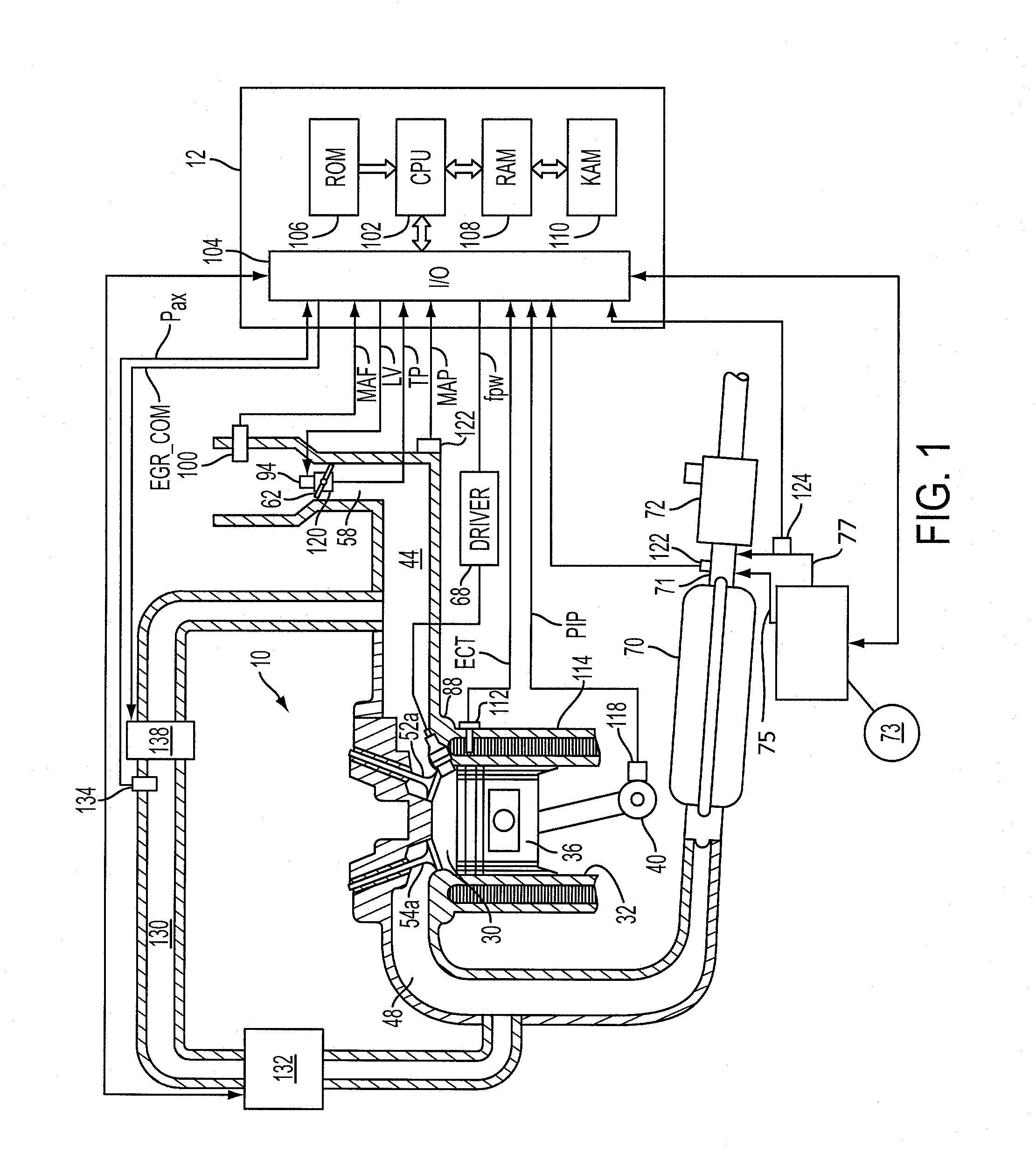
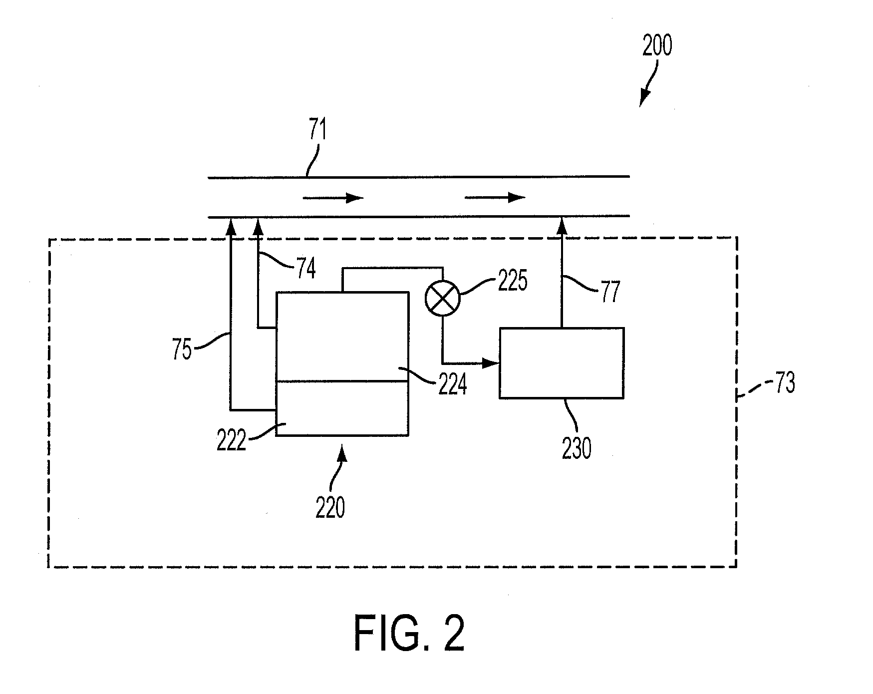
[0015]The accompanying figures and this description depict and describe various exemplary embodiments of a system for managing a plurality of reductants for use in an SCR process. The embodiments described herein include a first storage device for storing a first reductant that is added to the exhaust system upstream of a catalyst for the reduction of various engine emissions. Under certain conditions, the first reductant may react with atmospheric components such as water vapor, and / or may decompose, to form a second reductant. Over time, pressures of the second reductant in the first storage device may become elevated, which may cause an uncontrolled release of the second reductant from the first storage device. To help prevent such release, the embodiments described herein also include a second storage device for storing the second reductant. The second reductant stored in the second storage device may be used at least temporarily in parallel with, or separately from, the first r...


PUM

PropertyMeasurementUnit
concentrationaaaaaaaaaa
pressuresaaaaaaaaaa
pulse widthaaaaaaaaaa

Abstract

A method of operating a reductant delivery and storage system of a vehicle, comprising of storing an ammonia-containing fluid in a first storage device, generating ammonia vapors in the first storage device and storing said generated ammonia vapors in a second storage device, purging said stored vapors from the second storage device to an exhaust of the engine, delivering said ammonia-containing fluid to said exhaust of the engine, and adjusting at least one of an amount of ammonia-containing fluid delivered and an amount of vapors purged to said exhaust based on the other of said at least one of said amount of ammonia-containing fluid delivered and said amount of vapors purged to said exhaust.

Description

BACKGROUND AND SUMMARY[0001]Ammonia or urea may be stored on-board a vehicle for use as a reductant in exhaust emission control systems.[0002]Under some conditions, such as during engine starting, ammonia vapor that was generated in the reductant system may be used, such as described in U.S. 2006 / 0117741. For example, ammonia vapors may be routed to a storage unit and a reactor that uses exhaust heat or electrically generated heat. Further, the vapors may also be directed to the exhaust gas to react with exhaust gas NOx in a catalyst in the exhaust flow, while reductant stored in a separate tank may also be delivered to the exhaust.[0003]However, the inventors herein have recognized several issues with such a system. For example, a lack of coordination between vapor reductant and reductant delivered from the tank may result in insufficient reductant supply, or an over-supply of reductant. Further, uncertainties in the amount of vapors delivered may further exacerbate such issues, es...

Claims


Application Information

Patent Timeline
Patent Type & Authority Applications(United States)
IPC IPC(8): B01D53/94
CPCF01N3/208F01N2560/026Y02T10/24F01N2610/10F01N2610/146F01N2610/02Y02T10/12Y02A50/20
Inventor OBERSKI, CHRISTOPHERCAVATALO, GIOVANNIVAN NIEUWSTADT, MICHIEL J.WEBB, TIMOTHYRUONA, WILLIAM
Owner FORD GLOBAL TECH LLC
Why Eureka
Try Eureka