Magnetic-resonance image diagnostic apparatus and method of controlling the same

a magnetic resonance image and diagnostic apparatus technology, applied in the field of magnetic resonance image diagnostic apparatus, can solve the problems of insufficient phase dispersion of blood flow, insufficient signal level, image not demonstrating arteries more clearly, etc., and achieves the effect of high precision

Active Publication Date: 2008-03-20
TOSHIBA MEDICAL SYST CORP
View PDF15 Cites 34 Cited by
  • Summary
  • Abstract
  • Description
  • Claims
  • Application Information

AI Technical Summary

Benefits of technology

[0014] In view of the foregoing, it has been firstly desired that images should vis...

Problems solved by technology

Since the phase disperses in various ways in accordance with the velocity at which the blood flows, some blood flows may undergo insufficient phase dispersion and may not be represented by signals of sufficiently low level.
In some cases, the blood flows will result in artifacts.
However, these images do not visualize the arteries more clea...

Method used


Image

  • Magnetic-resonance image diagnostic apparatus and method of controlling the same
  • Magnetic-resonance image diagnostic apparatus and method of controlling the same
  • Magnetic-resonance image diagnostic apparatus and method of controlling the same

Examples


first embodiment

[0073] The first embodiment will be described. The first embodiment is designed to achieve the first desire.

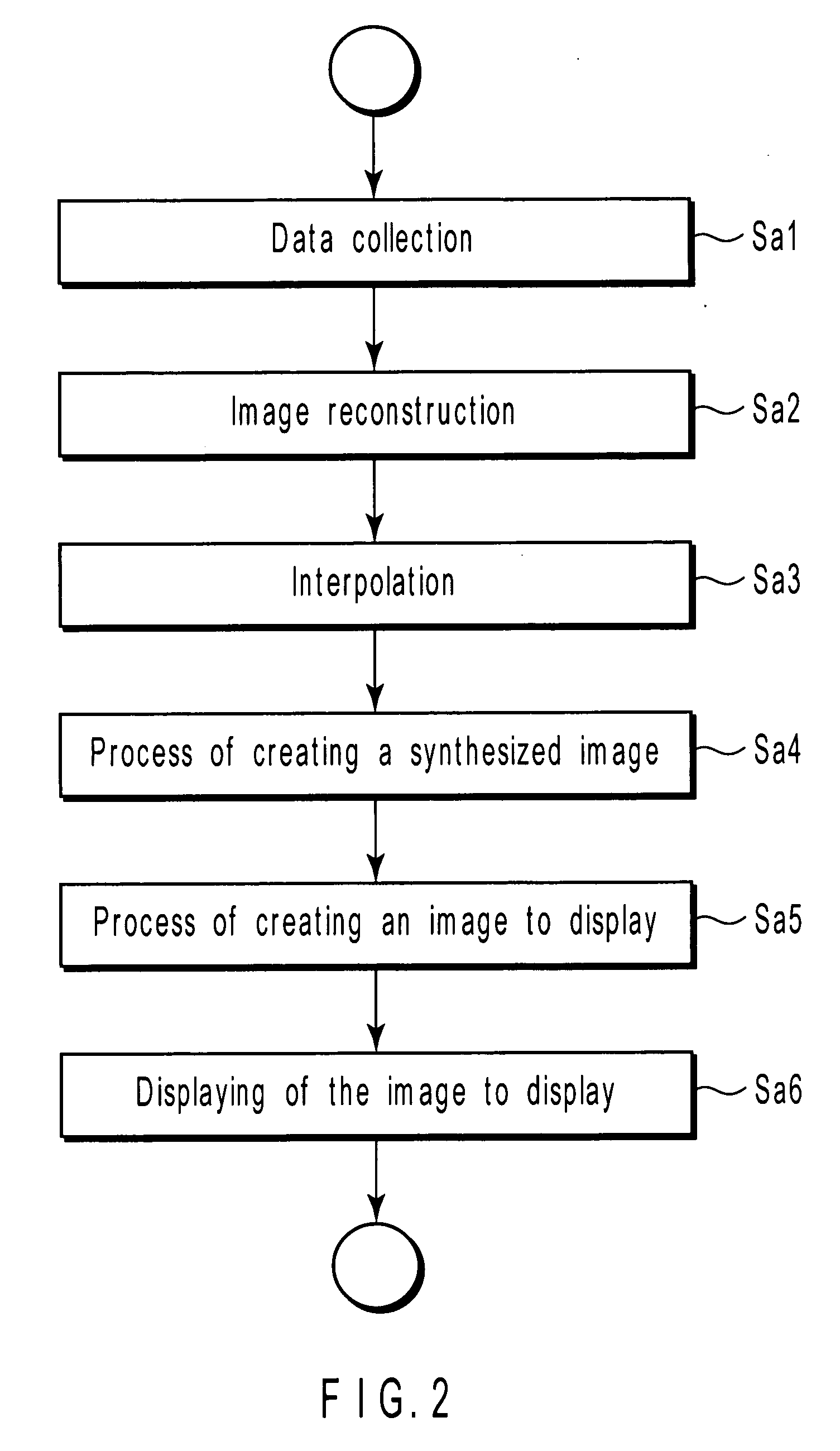
[0074]FIG. 2 is a flowchart explaining the sequence of processes the host computer 16 performs in the first embodiment to provide images.

[0075] In Step Sa1, the host computer 16 instructs the sequencer 10 to collect data. Upon receiving the instruction, the sequencer 10 collects data as will be explained below.

[0076]FIG. 3 is a diagram visualizing the pulse sequence in the first embodiment. FIG. 3 shows the waveform of a radio-frequency pulse (RF), the waveform of a gradient magnetic field (Gss), the waveform of another gradient magnetic field (Gpe), the waveform of a gradient magnetic field (Gro) and the waveform of an echo signal (Echo), in descending order. The pulse (RF) is applied to the object to be imaged. The wave (Gss) extends in the slice direction, the wave (Gpe) in the phase encode direction, and the wave (Gro) in the read-out direction.

[0077] As seen from FIG....

second embodiment

[0117] The second embodiment will be described. The second embodiment is designed to achieve the second desire.

[0118]FIG. 12 is a diagram visualizing the pulse sequence in the second embodiment. More precisely, this figure shows the waveform of a radio-frequency pulse (RF), the waveform of a gradient magnetic wave (Gss), the waveform of another gradient magnetic wave (Gpe), the waveform of a gradient magnetic wave (Gro) and the waveform of an echo signal (Echo), in descending order. The pulse (RF), gradient magnetic waves (Gss, Gpe and Gro) and echo signal (Echo) are applied to the object to be imaged. The wave (Gss) extends in the slice direction, the wave (Gpe) in the phase encode direction, and the wave (Gro) in the read-out direction.

[0119] As seen from FIG. 12, the pulse sequence used in the second embodiment accords with the gradient echo method. The second embodiment differs from the first embodiment in that rephasing is performed for the echo time as disclosed in the refer...

third embodiment

[0122] The imaging method used in the magnetic resonance imaging diagnostic apparatus 100 according to the first embodiment, i.e., the imaging method using a pulse sequence for the gradient echo system, which includes a dephase gradient-magnetic-field pulse, will be hereinafter referred to as flow-sensitive black blood (FSBB) imaging.

[0123] In the FSBB imaging, the phase of each flow such a blood flow, which is a motion, is gradually distributed, and the vector sum of the flow spins gradually decreases. That is, the amplitude component of the flow signal is gradually attenuated. As a result, the signal of the flow is suppressed and an image will be obtained, in which any blood vessel is represented by a low-level signal. Generally, a b-factor is used, which indicates a dephase amount. The b-factor is a tensor amount defined by equations (2) and (3) above.

[0124] In equation (3), γ is a gyromagnetic ratio of about 2π×42.6 MHz / T, and G(t) is a gradient-magnetic-field waveform vector....


PUM


Abstract

A magnetic resonance imaging diagnostic apparatus includes a generating unit which generates a slice gradient magnetic field, a phase-encode gradient magnetic field and a read-out gradient magnetic field that extend in a slice axis, a phase-encode axis and a read-out axis, respectively, a setting unit which sets a dephase amount for weighting a signal-level decrease resulting from flows in the arteries and veins present in a region of interest of a subject, with respect to at least one axis selected form the slice axis, phase-encode axis and read-out axes, and a control unit which controls the generating unit by using a pulse sequence for a gradient echo system, which includes a dephase gradient-magnetic-field pulse that corresponds to the dephase amount set by the setting unit for the at least one axis.

Description

CROSS-REFERENCE TO RELATED APPLICATIONS [0001] This application is based upon and claims the benefit of priority from prior Japanese Patent Applications No. 2006-248402, filed Sep. 13, 2006; and No. 2007-133193, filed May 18, 2007, the entire contents of both of which are incorporated herein by reference. BACKGROUND OF THE INVENTION [0002] 1. Field of the Invention [0003] The present invention relates to a magnetic resonance image diagnostic apparatus fit for providing susceptibility-weighted images of the interior of, for example, the head, and also to a method of controlling the apparatus. [0004] 2. Description of the Related Art [0005] T2*-weighted images acquired by the gradient echo method acutely reflect the non-uniformity of a local magnetic field. Therefore, the gradient echo method is widely used as an imaging method for visualizing a difference between regions of interests in terms of susceptibility. In order to provide T2*-weighted images of the subject's head, rephasing ...

Claims


Application Information

Patent Timeline
IPC IPC(8): A61B5/05
CPCG01R33/543G01R33/5602G01R33/5607G01R33/56509G01R33/56316G01R33/5635G01R33/5611G01R33/5615G01R33/56545
Inventor IKEDO, MASATOKIMURA, TOKUNORI
Owner TOSHIBA MEDICAL SYST CORP
Why Eureka
Try Eureka