Permanent magnet rotor type motor and method for manufacturing the same

Inactive Publication Date: 2008-03-27
LG ELECTRONICS INC
View PDF5 Cites 41 Cited by
  • Summary
  • Abstract
  • Description
  • Claims
  • Application Information

AI Technical Summary

Benefits of technology

[0059]Firstly, heat generated from the PCB, more particularly, heat generated from the powered device provided at the PCB, can be efficiently emitted without separate heat-emission means. Also, the permanent magnet rotor type motor of the present invention can be easily manufactured with a simplified method.
[0060]Secondly, as a result of strongly securing the PCB to the bracket while electrically connecting the PC

Problems solved by technology

This may result in a great amount of loss and heat emission in the powered devices.
However, when controlling the operation of the motor based on the above described PWM manner, there still exists loss by the inverter.
The largest part of the loss is a switching loss that is caused as the switch devices, i.e. powered devices of the inverter are periodically switched.
First, if the powered devices are switched on to allow current I to flow therethrough, the flow of the current I is partially limited by the internal resistance of the powered devices as well as the overall load resistance.
However, as shown in FIG. 4, during a transition time period of switching on and off the powered devices, the powered devices are affected by both t

Method used


Image

  • Permanent magnet rotor type motor and method for manufacturing the same
  • Permanent magnet rotor type motor and method for manufacturing the same
  • Permanent magnet rotor type motor and method for manufacturing the same

Examples


Embodiment Construction

[0071]Reference will now be made in detail to the preferred embodiments of the present invention, examples of which are illustrated in the accompanying drawings. Wherever possible, the same reference numbers will be used throughout the drawings to refer to the same or like parts.

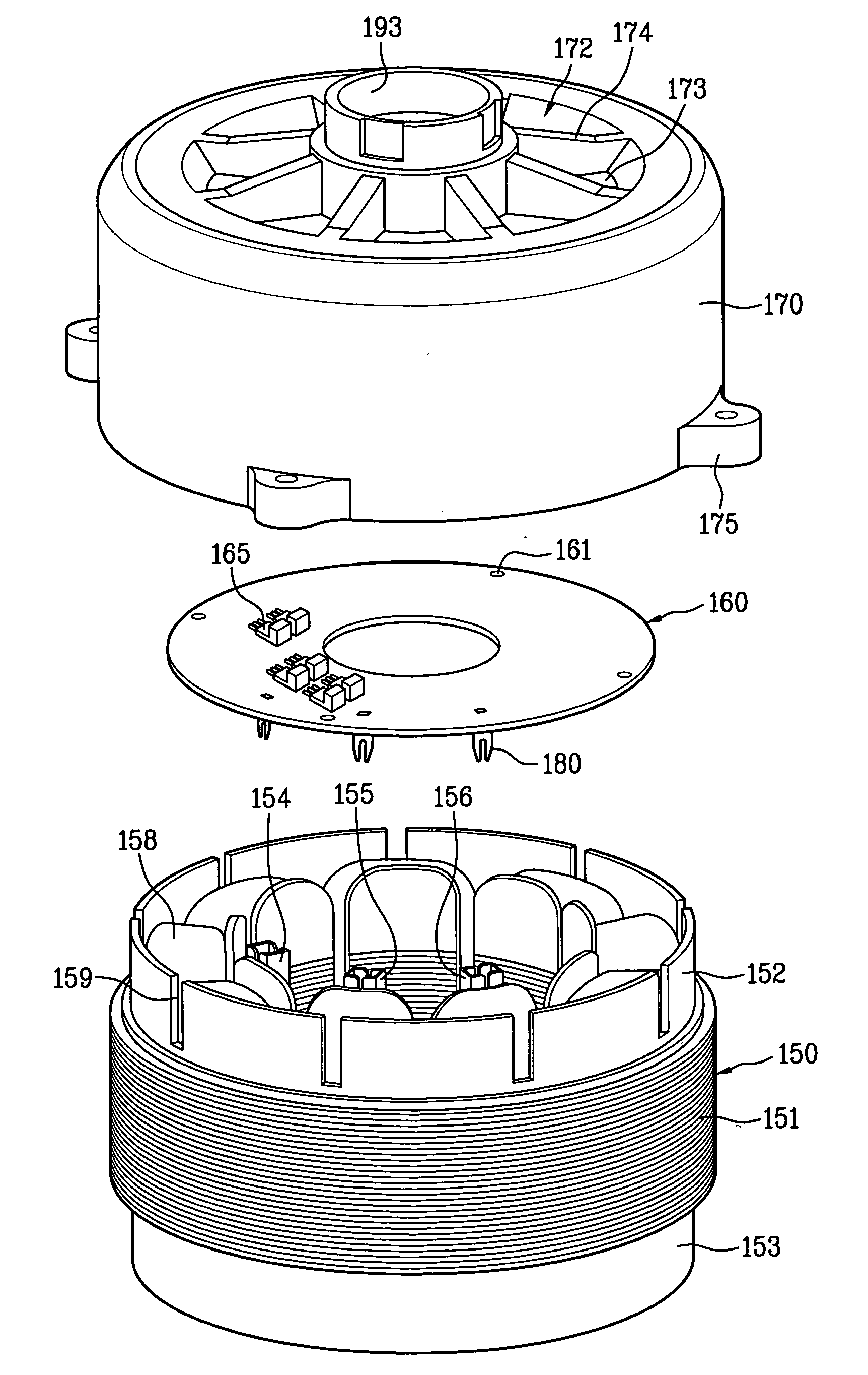
[0072]Now, a permanent magnet rotor type motor according to the present invention will be explained in detail with reference to FIGS. 5 to 7.

[0073]First, a bracket included in the permanent magnet rotor type motor according to the present invention will be described in detail.

[0074]The bracket is configured to receive a stator 150, a rotor (not shown), a PCB 160, and the like therein and defines the overall outer appearance of the motor. The bracket is integrally formed with a heat-emitting portion 172, so as to emit heat generated in the motor through the heat-emitting portion 172.

[0075]The bracket may be divided into an upper bracket portion 170 and a lower bracket portion 171. The upper and lower bracket ...


PUM


Abstract

Disclosed is a permanent type motor in which a permanent magnet is attached to or embedded in a rotor in a rotatable manner. More particularly, a permanent magnet rotor type motor, which can be easily manufactured while achieving an improvement in heat-emission performance, is disclosed. The permanent magnet rotor type motor includes a stator having a stator coil would about an insulator, a printed circuit board (PCB) secured to an upper portion of the stator and having a powered device mounted on the PCB, and a bracket having a heat-emitting portion formed at an upper surface of the bracket, the bracket being configured to receive the stator and the PCB such that the powered device comes into contact with the heat-emitting portion.

Description

[0001]This application claims the benefit of the Korean Patent Application No. 10-2006-0093466 filed on Sep. 26, 2006, No. 10-2006-0093467 filed on Sep. 26, 2006 and No. 10-2006-0093973 filed on Sep. 27, 2006 which are hereby incorporated by reference as if fully set forth herein.BACKGROUND OF THE INVENTION[0002]1. Field of the Invention[0003]The present invention relates to a permanent magnet rotor type motor in which a permanent magnet is attached to or embedded in a rotor in a rotatable manner. More particularly, the present invention relates to a permanent magnet rotor type motor which can be easily manufactured while achieving an improvement in heat-emission performance.[0004]2. Discussion of the Related Art[0005]A representative example of permanent magnet rotor type motors is a brushless DC (BLDC) motor. The BLDC motor is an adjustable speed motor capable of easily controlling a rotating speed and rotating direction, and is mainly used as drive devices of home electronics, et...

Claims


Application Information

Patent Timeline
IPC IPC(8): H02K9/00H02K3/24H02K11/00H02K5/00
CPCH02K5/18H02K11/0073H02K9/22H02K11/33H02K9/223
Inventor LEE, SEON JOONG
Owner LG ELECTRONICS INC
Why Eureka
Try Eureka