Inductor topologies with substantial common-mode and differential-mode inductance

a topology and differential mode technology, applied in the direction of inductance, continuous variable inductance/transformer, core/yokes, etc., can solve the problem that the single traditional inductor is not effective in simultaneously filtering both cm and dm noise, and achieve the effect of reducing the size, weight, and complexity of the electromagnetic interference filtering circui

Inactive Publication Date: 2008-03-27
FORD GLOBAL TECH LLC
View PDF15 Cites 20 Cited by
  • Summary
  • Abstract
  • Description
  • Claims
  • Application Information

AI Technical Summary

Benefits of technology

[0009]In addition, the present invention reduces the size, weight, and complexity of an electromagnetic interference filtering circuit and as such the costs associated therewith.

Problems solved by technology

A single traditional inductor is not effective in simultaneously filtering both CM and DM noises, due to the structure thereof.

Method used


Image

  • Inductor topologies with substantial common-mode and differential-mode inductance
  • Inductor topologies with substantial common-mode and differential-mode inductance
  • Inductor topologies with substantial common-mode and differential-mode inductance

Examples


Embodiment Construction

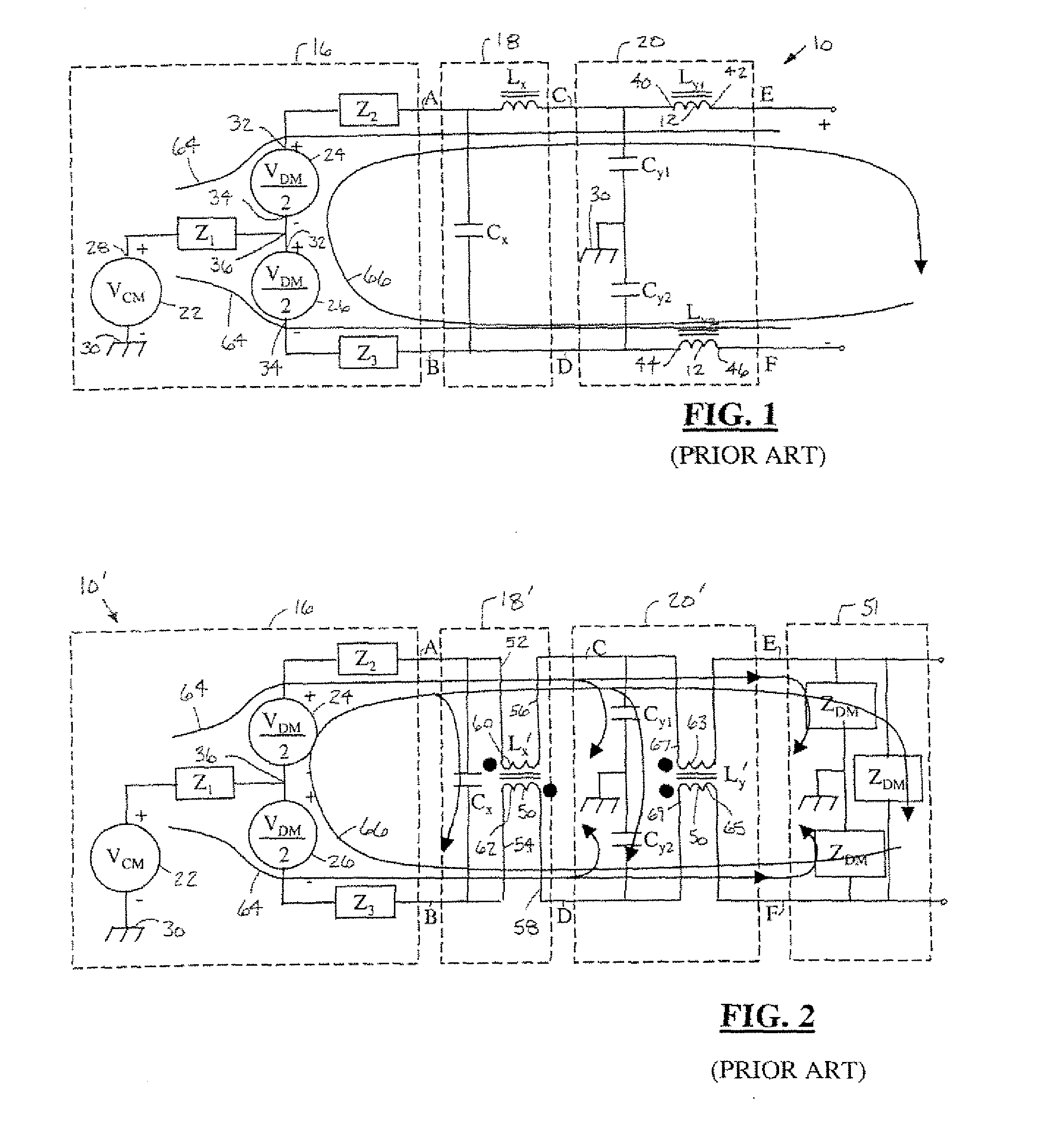
[0027]In the following described FIGS. 1 and 2 typical common mode (CM) and differential-mode (DM) filter topologies are shown for the reduction of electromagnetic interference (EMI) noise emission. FIG. 1 illustrates a simple filter topology that includes capacitors and inductors without mutually coupled windings. FIG. 2 illustrates a filter topology with inductors that have mutually coupled windings.

[0028]Referring now to FIG. 1, a schematic view of a traditional electronic circuit 10 that incorporates CM and DM filtering, with inductors 12 that have single-coupled windings, is shown. The circuit 10 includes an EMI source circuit 16 and a pair of inductor-based filtering circuits, namely, a DM filtering circuit 18, and a CM filtering circuit 20.

[0029]The EMI source circuit 16 has a CM source 22, which represents CM EMT noise generated by EMI circuit 16, and a pair of DM sources 24, 26, which represent DM EMI noise generated by EMI circuit 16. The CM source 22 has a CM terminal 28 ...


PUM

PropertyMeasurementUnit
conductiveaaaaaaaaaa
magnetic internal fluxaaaaaaaaaa
switching speedaaaaaaaaaa

Abstract

An inductor (160) includes a core (162) that has a window (164). The core (162) includes a first core member (168) and a second core member (170). A first winding (176) is coupled to the first core member (168) and a second winding (178) is coupled to the second core member (170). A cross-member (172, 174) is coupled at least partially across the window (178) and is conductively enabling flux flow between the first core member (168) and the second core member (170). An electronic circuit (100) includes an input terminal (118), an inductor (102), and an output terminal (E′, F′). The inductor (102) is coupled to the input terminal and has only a single inductive core (162). The inductor (102) is coupled to filter both common-mode noise and differential-mode noise. The load terminal is coupled to and receives filtered common-mode and differential-mode current from the inductor (102).

Description

TECHNICAL FIELD[0001]The present invention relates to vehicle and non-vehicle electronic and electrical systems and components. More particularly, the present invention is related to inductor topologies for common-mode and differential-mode filtering circuits and the like.BACKGROUND OF THE INVENTION[0002]A variety of power converters are used throughout industry. Power converters are often utilized in electronic circuits for direct current (DC) or alternate current (AC) conversion to supply power to electric motors. Such conversion is performed on hybrid electric vehicles, fan drives, washing machines, refrigerators, and other various machines and equipment to improve efficiency and performance, as well as to minimize noise.[0003]Certain electronic circuits exhibit high switching speeds. At high switching speed, the electronic circuits generate common-mode (CM) and differential-mode (DM) electromagnetic interference (EMI) noises. Thus, CM and DM filters are incorporated to remove su...

Claims


Application Information

Patent Timeline
Patent Type & Authority Applications(United States)
IPC IPC(8): H01F21/08
CPCH01F3/12H01F3/14H01F27/38H01F37/00H03H2001/005H01F2017/0093H01F2017/065H03H7/427H01F38/023
Inventor CHEN, CHINGCHIDEGNER, MICHAELLIANG, FENG
Owner FORD GLOBAL TECH LLC
Why Eureka
Try Eureka