Dual-frequency high-gain antenna

a high-gain antenna and dual-frequency technology, applied in the direction of individual energised antenna arrays, resonant antennas, radiating element structural forms, etc., can solve the problems of insufficient bandwidth and gain, difficult integration, and the inability to provide a dual-frequency high-gain antenna to improve the signal transmission bandwidth. , to achieve the effect of increasing the signal transmission distance and improving the gain and bandwidth of the antenna

Inactive Publication Date: 2008-03-27
SMARTANT TELECOMM
View PDF4 Cites 24 Cited by
  • Summary
  • Abstract
  • Description
  • Claims
  • Application Information

AI Technical Summary

Benefits of technology

[0008]In view of the above, the main objective of the present invention is to provide a dual-frequency high-gain antenna, which utilizes the design of a diplexer loop portio

Problems solved by technology

However, in general, the dual-frequency antenna has the disadvantages of being insufficient in bandwidth and gain and has the problem of being difficult to integrate.
T

Method used


Image

  • Dual-frequency high-gain antenna
  • Dual-frequency high-gain antenna
  • Dual-frequency high-gain antenna

Examples


first embodiment

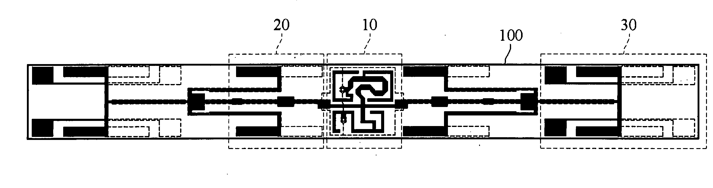
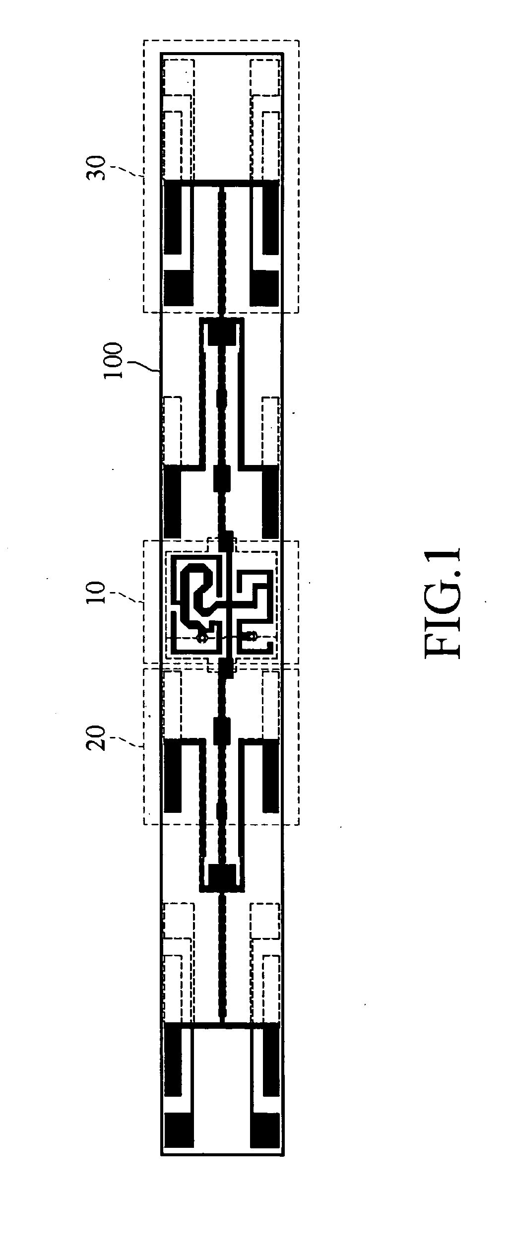
[0049]Referring to FIG. 1, it is a schematic view of the appearance of an antenna substrate according to the present invention. The antenna substrate 100 is provided with a diplexer loop portion 10, two single-frequency radiation units 20 and two dual-frequency radiation units 30.

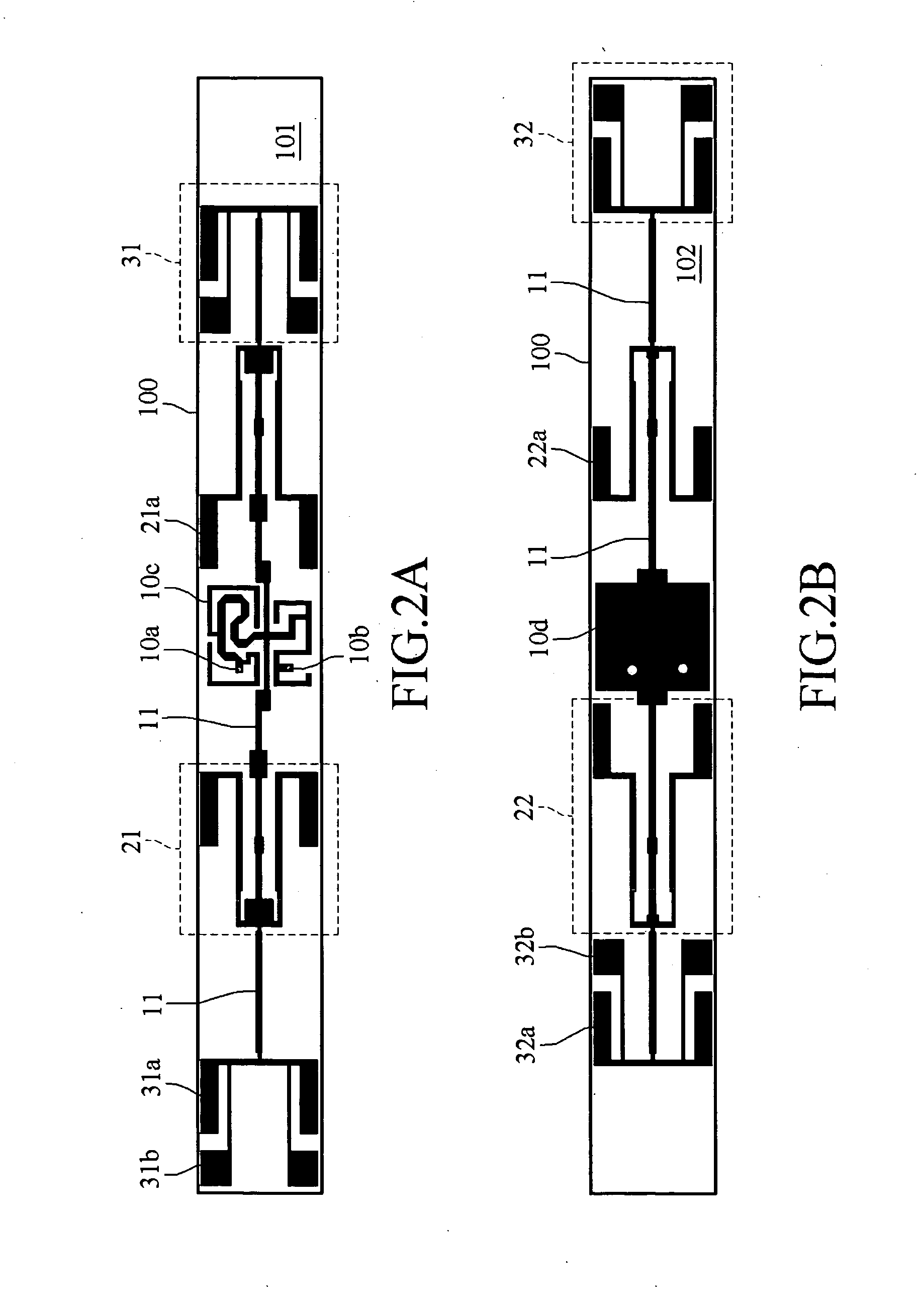
[0050]The diplexer loop portion 10 includes two signal feed portions, i.e., a first signal feed portion 10a and a second signal feed portion 10b (as shown in FIG. 2A). The first signal feed portion 10a and the second signal feed portion 10b are respectively connected to a corresponding meandering microstrip line section 10c for providing a signal transmitting path and a signal receiving path, and filtering out a transmitting signal and a receiving signal through a filtering line (not shown).

[0051]The two single-frequency radiation units 20 are respectively disposed on two sides of the diplexer loop portion 10 and connected to the diplexer loop portion 10 through a microstrip line for receiving and radiating...

second embodiment

[0062]Referring to FIG. 2C, it is a front view of the appearance of the antenna substrate according to the present invention. The antenna substrate 100 is provided with a diplexer loop portion 10 and two dual-frequency radiation portions 30.

[0063]The diplexer loop portion 10 includes two signal feed portions, i.e., a first signal feed portion 10a and a second signal feed portion 10b, wherein the first signal feed portion 10a and the second signal feed portion 10b are respectively connected to a corresponding meandering microstrip line section 10c for providing a signal transmitting path and a signal receiving path, and filtering out a transmitting signal and a receiving signal through a filtering line (not shown).

[0064]The dual-frequency radiation units 30 are connected to the diplexer loop portion 10 through the microstrip line for receiving and radiating a feed signal. Each dual-frequency radiation unit 30 includes a first frequency band radiation portion 30a and a second frequenc...


PUM


Abstract

A dual-frequency high-gain antenna is provided, which includes: a diplexer loop portion disposed at the center of the antenna substrate for receiving a feed signal; two single-frequency radiation units, symmetrically connected to two sides of the diplexer loop portion for radiating a radio-frequency signal corresponding to a first frequency value of the feed signal; and two dual-frequency radiation units, respectively connected to each single-frequency radiation portion for radiating radio-frequency signals corresponding to the first frequency value and a second frequency value of the feed signal.

Description

BACKGROUND OF THE INVENTION[0001]1. Field of Invention[0002]The present invention relates to a printed circuit board (PCB) antenna, and more particularly to a dual-frequency high-gain antenna.[0003]2. Related Art[0004]Along with the development of wireless communication technology, information can be transmitted by a wireless communication system without the limitation of geography. Being one of the most important elements in the wireless communication field, the current antenna is preferably fabricated by means of PCB with various advantages such as being simple and low in cost.[0005]At present, the standard of wireless transmission is constituted by the Institute of Electrical and Electronics Engineers (IEEE), so as to make the wireless transmission technology widely utilized, and ensure that the devices produced by various manufacturers are compatible and stable.[0006]In an ordinary radio-frequency circuit, passive parts are frequently used, such as antenna, diplexer, high low ba...

Claims


Application Information

Patent Timeline
IPC IPC(8): H01Q21/00
CPCH01Q1/38H01Q9/285H01Q5/40H01Q21/30H01Q21/08
Inventor SONG, JIA-JIUCHENG, WEI-TONG
Owner SMARTANT TELECOMM
Why Eureka
Try Eureka