
PTT system, method for implementing PTT communication, PTT management server and terminal device thereof

a ptt management server and ptt technology, applied in the field of ptt, can solve the problems of ptt (or poc) solutions that existing ptt (or poc) solutions are too complicated, and can only provide audio communication and cannot provide video and data communication, etc., to achieve the effect of reducing costs, reducing bandwidth, and simple networkwork

Inactive Publication Date: 2008-03-27
LENOVO (BEIJING) CO LTD
View PDF4 Cites 4 Cited by
  • Summary
  • Abstract
  • Description
  • Claims
  • Application Information

AI Technical Summary

Benefits of technology

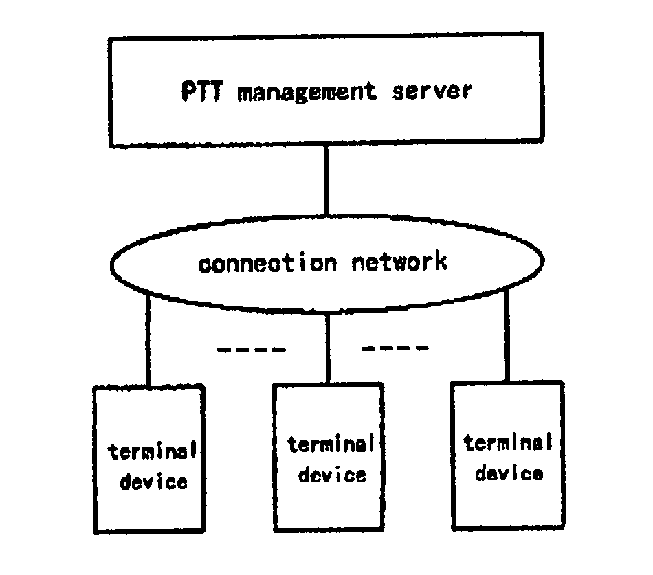
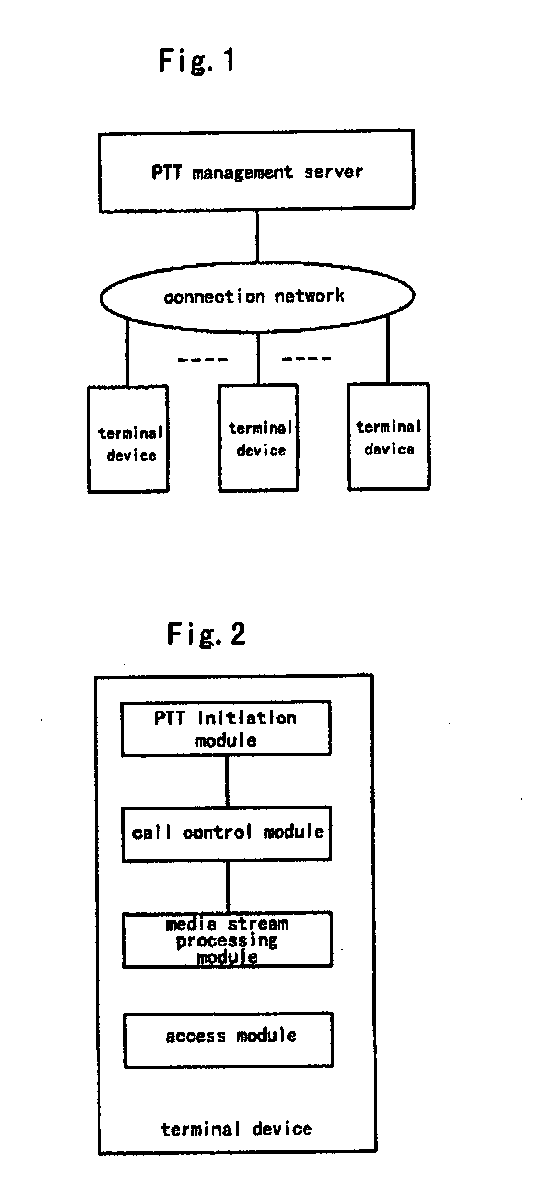
[0012] To solve the problems in the solutions for the existing PTT system, an object of the present invention is to provide a PTT system, a method for implementing PTT communication, a PTT management server and a terminal device, which can implement PTT transmission of audio, image, data, etc. with a simple network structure.
[0057] The PTT is implemented via WiFi / WiMAX or Intranet within an enterprise, without need of a POC service provided by an operator, which can reduce cost greatly while ensuring the user experience.
[0058] The effect of the PTT on bandwidth is minimized by utilizing a multicast technique for improving transmission efficiency of the PTT;
[0059] The network bandwidth within an enterprise is much higher than that of a cellular network, which can achieve better quality of audio and to provide PTT service for video and data simultaneously.

Problems solved by technology

However, the existing PTT techniques have problems of the following aspects:
The existing PTT (or PoC) solutions can only provide audio communication and can not provide video and data communication;
The existing PTT (or PoC) solutions are too complicated, and are not suitable for deployment and implementation in an enterprise;

Method used


Image

  • PTT system, method for implementing PTT communication, PTT management server and terminal device thereof
  • PTT system, method for implementing PTT communication, PTT management server and terminal device thereof
  • PTT system, method for implementing PTT communication, PTT management server and terminal device thereof

Examples


Embodiment Construction

[0064] Before the present invention is explained in detail, some basic conceptions involved in the present invention are explained in order to better describe the detail implementation of the present invention.

[0065] A call is a multimedia communication process initiated by one terminal device and participated in by a plurality of terminal devices. In each call process, only one terminal device can send information, and other terminal devices receive information.

[0066] A terminal device transmitting a call is a source terminal device and a terminal device receiving a call is a destination terminal device.

[0067] A user group consists of all the terminal devices participating in the call, including at least one of source terminal devices and one or more destination terminal devices.

[0068] A media stream is a set of data stream in the form of audio and / or video and / or data transmitted in the call;

[0069] An uplink media stream is a media stream transmitted from the source terminal ...


PUM


Abstract

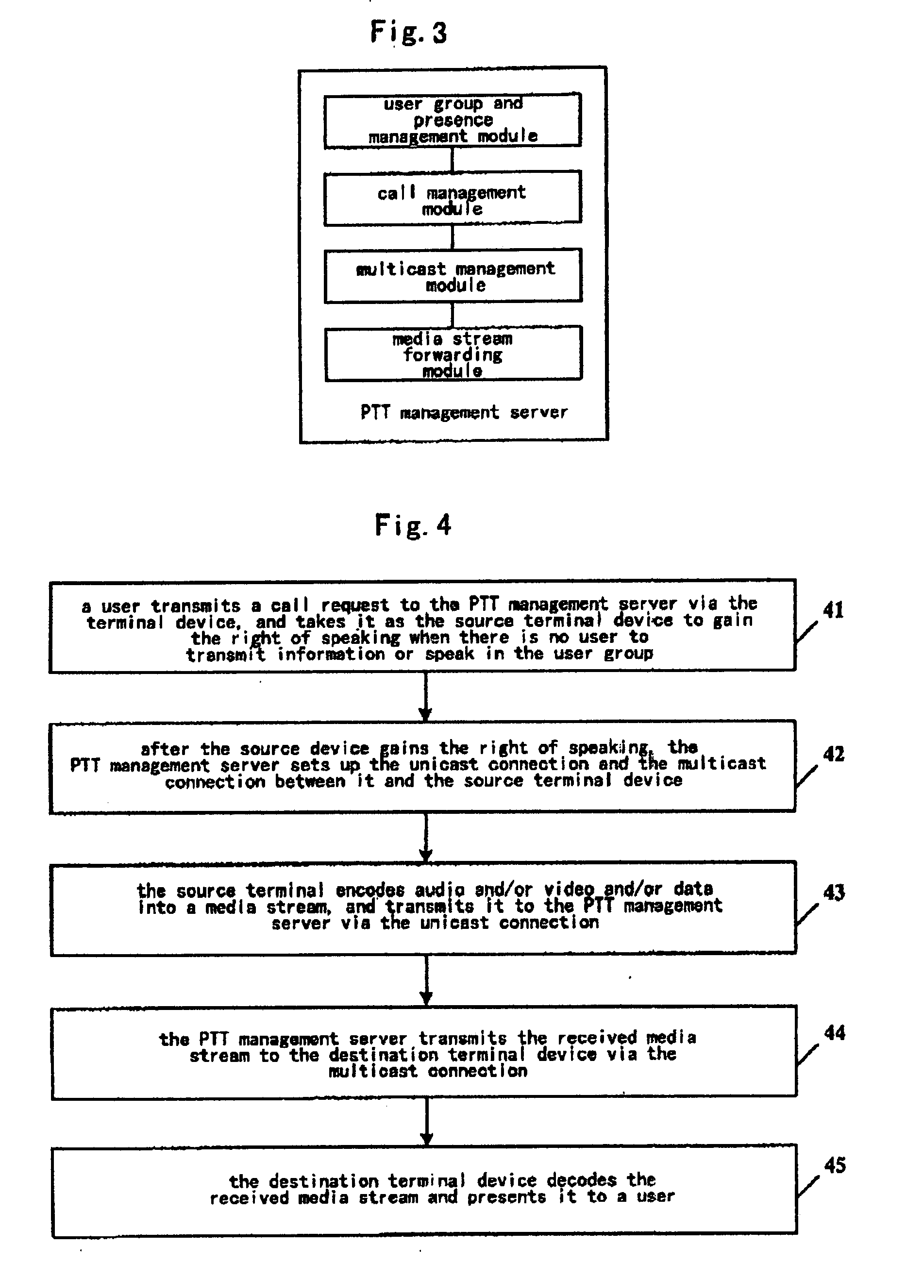
A PTT system comprises a plurality of terminal devices and a PTT management server interacting via a connection network. The PTT management server is configured to set up a unicast connection between the PTT management server and a source terminal device and a multicast connection between the PTT management server and a destination terminal device according to a call request from the source terminal device; and to receive an uplink media stream and transmit a downlink media stream. The unicast connection is used for transmission of the uplink media stream from the source terminal device to the PTT management server, and the multicast connection is used for transmission of the downlink media stream from the PTT management server to the destination terminal device. The present invention can implement PTT transmission of audio, image, data, etc. with a simple network structure.

Description

BACKGROUND OF THE INVENTION [0001] 1. Field of Invention [0002] The present invention relates to a technique of Push to Talk (PTT), and more particularly a technique of implementing PTT by using enterprise intranet. [0003] 2. Description of Prior Art [0004] PTT means to use a mobile phone with a corresponding function as a walkie-talkie, which is a half-duplex manner of communication. Such a mobile phone has a talk key, and a user may communicate with other users or a group when it is pressed (wherever far or near, it only needs that they are within a coverage of an operator's network). Simply speaking, PTT is a mobile phone with a “push to talk” function, which combines the function of mobile phone with that of walkie-talkie, thereby to implement PTT with the existing mobile communication network. [0005] The PTT mobile phone is different from the general walkie-talkie. Firstly, the walkie-talkie doesn't need to work via the network, while PoC (Push-To-Talk over Cellular) communicat...

Claims


Application Information

Patent Timeline
IPC IPC(8): H04B1/38H04W4/10
CPCH04W76/005H04W4/10H04W76/45H04L12/185H04L12/189H04L65/1101
Inventor TIAN, RIHUI
Owner LENOVO (BEIJING) CO LTD
Learn More