Method and device for lining pipe

a technology of lining pipe and pipe body, which is applied in the direction of shaft lining, shaft equipment, mechanical equipment, etc., can solve the problems of unwanted holes in the liner which may leak at the damaged portion, the connection between the bladder and the liner must be frangible, and the problem of affecting the repair effect of the pipe, so as to reduce the chance of pipe blockage, and reduce the effect of solid accumulation

Inactive Publication Date: 2008-04-03
LMK TECH LLC
View PDF24 Cites 14 Cited by
  • Summary
  • Abstract
  • Description
  • Claims
  • Application Information

AI Technical Summary

Benefits of technology

[0007]A further feature or advantage of the present invention is a device for lining pipe which reduces solids accumulation and thus reduces chance for blockage of pipe repairs.
[0008]A further feature or advantage of the present invention is a method of lining pipe which reduces blockage in the pipe being repaired.
[0009]Another feature or advantage of the present invention is a method of frangibly connecting a liner tube to an elongated positioning tube or an inversion bladder where the frangible attachment is strong during placement of the liner, yet can be easily broken or separated during removal of the positioning tube or bladder once th...

Problems solved by technology

One problem, however, with this type of pipe repair is that the edges of the liner create ridges inside the pipe where solids can collect and create blockage inside the pipe.
This is particularly problematic on the edge at the upstream end of the liner.
However, to remove the bladder, the connection between the bladder and the liner must be frangible.
Stitching the fabr...

Method used


Image

  • Method and device for lining pipe
  • Method and device for lining pipe
  • Method and device for lining pipe

Examples


Embodiment Construction

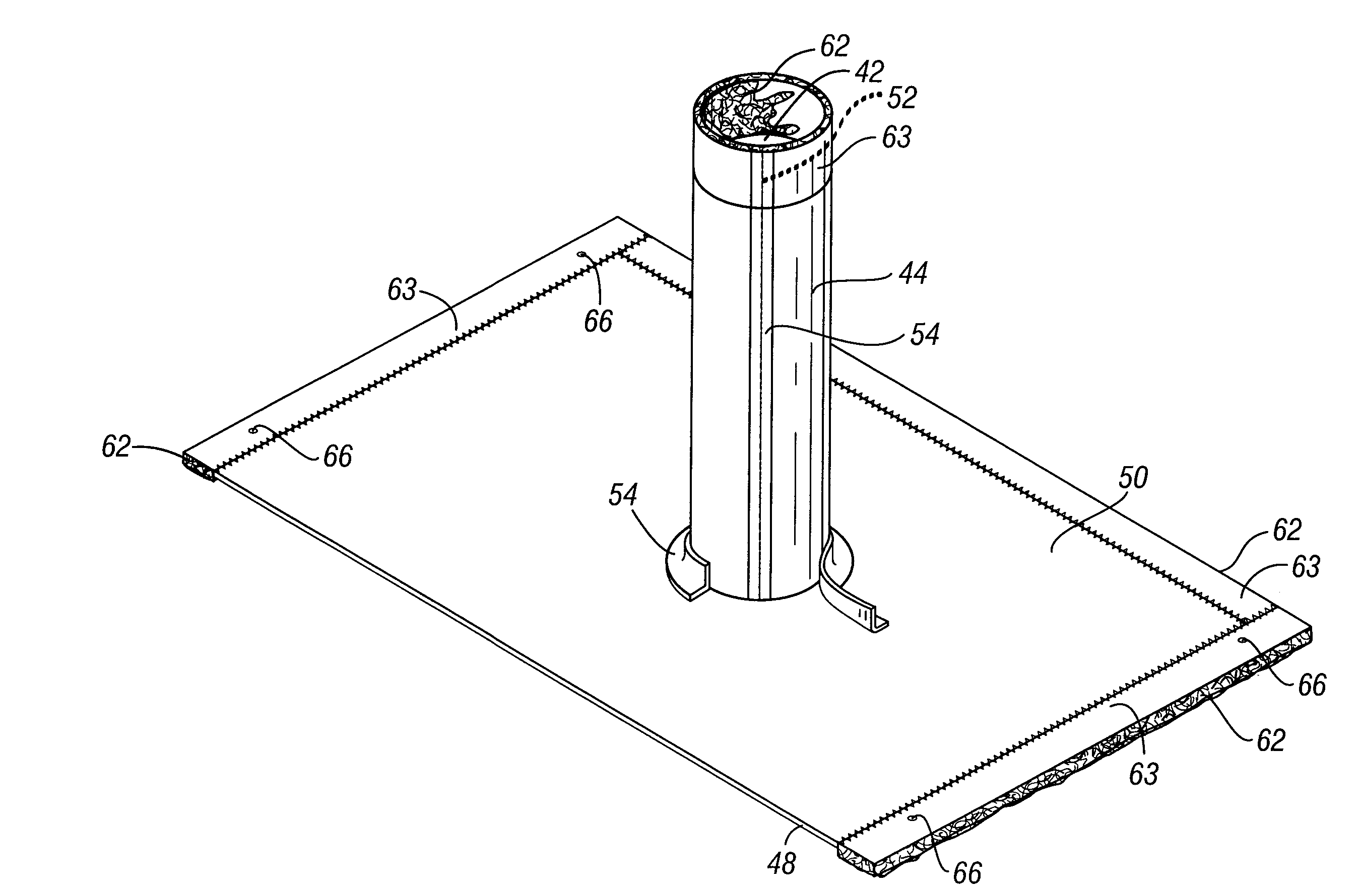
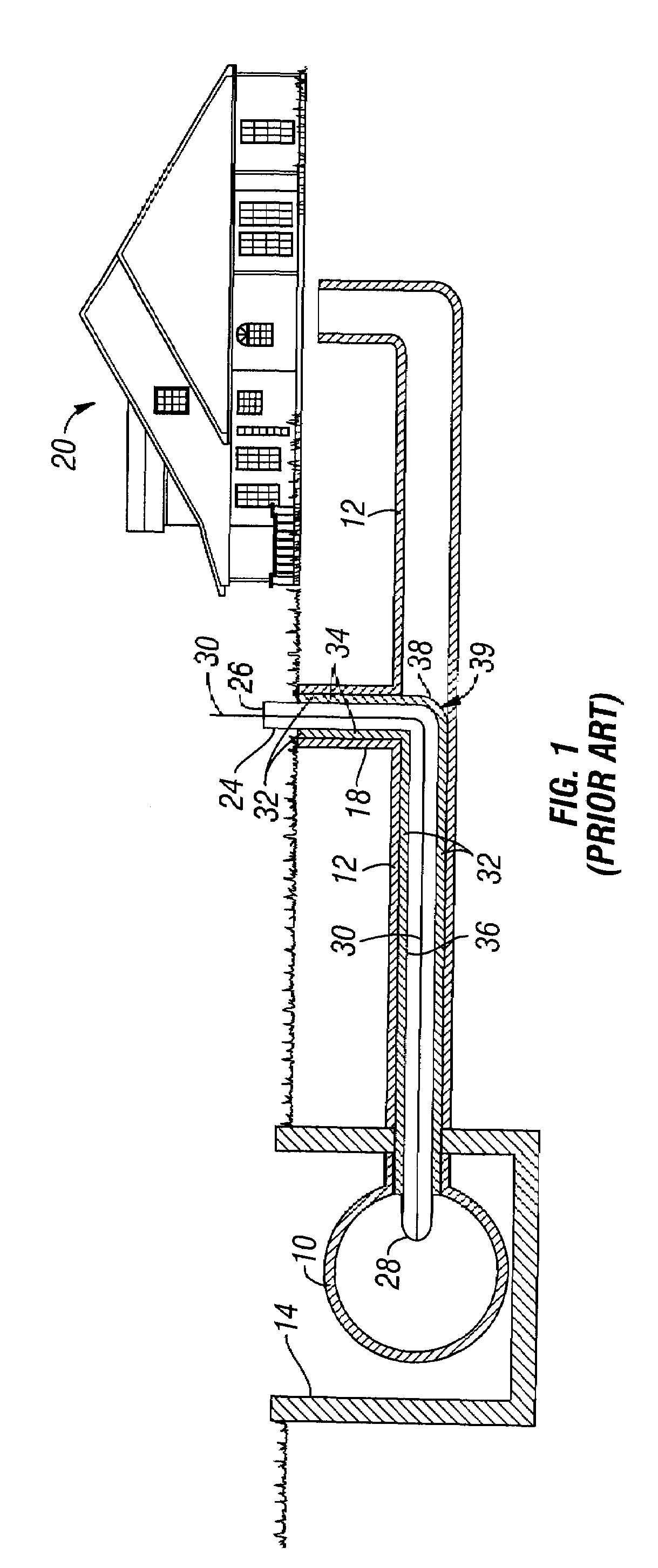
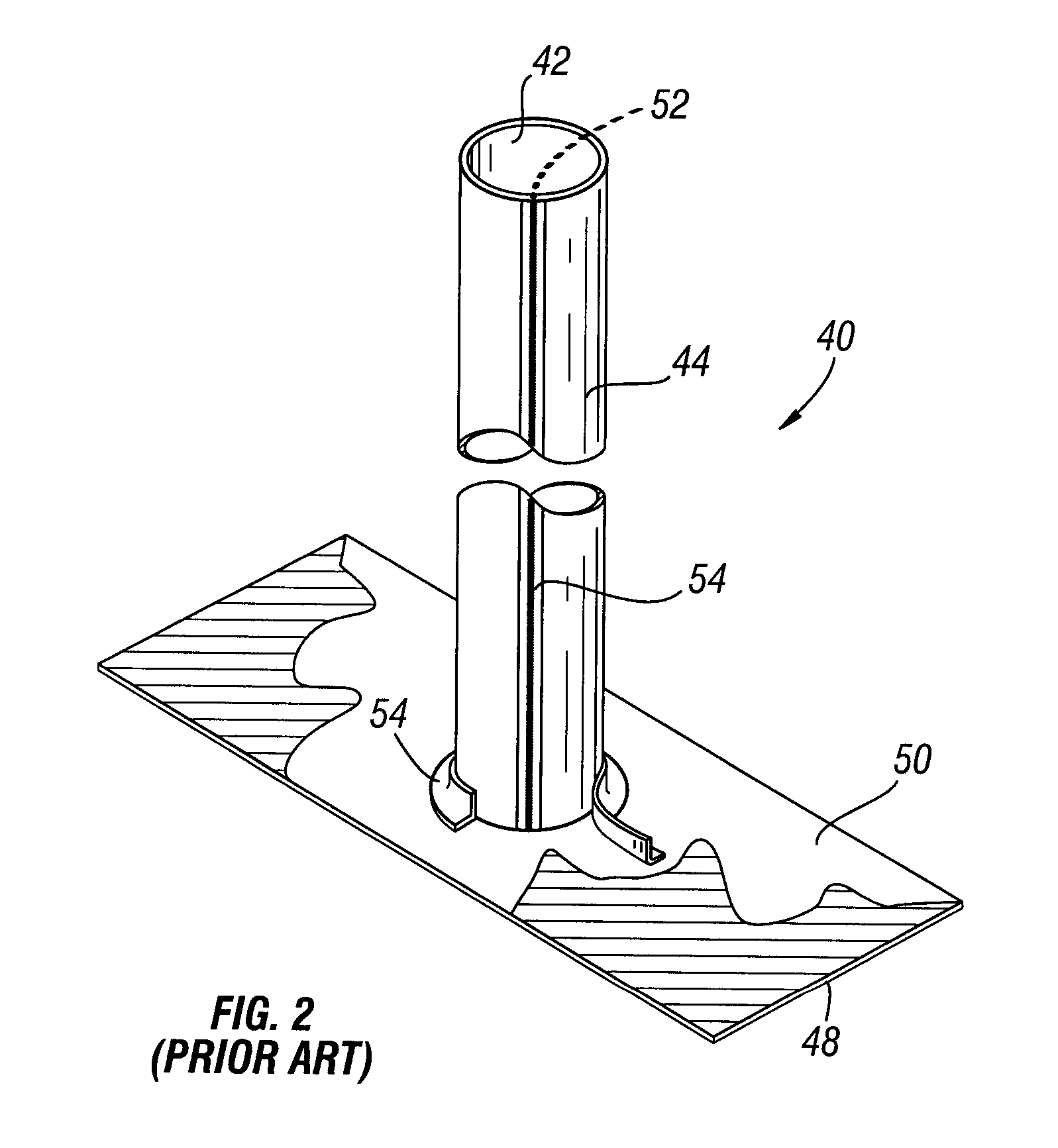
[0026]Typical prior art pipe repairs are shown in FIGS. 1-4. FIG. 1 shows a continuous liner tube 32 from the insertion point of the access or cleanout pipe 18 through the lateral pipe 12 to the main sewer pipe 10. FIG. 2 shows a liner assembly used for repairing pipe junctions such as at a main sewer line 10 / lateral sewer line 12 junction or at a lateral sewer line 12 / cleanout 18 junction. FIG. 3 shows one method for inserting a tube liner 32 into a partial section of lateral line 12 using an air pressure driven inversion process. Other types of positioning devices (not shown) can also be used to locate the liner 30 inside the pipe 10, 12 as would readily be understood by those skilled in the art. FIG. 4 shows a tube liner 32 curing in place to repair a partial section of a lateral line 12.

[0027]The liner 32 may or may not have an outer polymer-type coating 31. If the liner 32 has an outer coating 31 and the liner 32 is pulled into place, the resin impregnated into the lining 32 wi...


PUM


Abstract

The present invention is a new liner assembly for use in pipes constructed from a flexible liner formed from a resin absorbent material. A compressible material, such as stitch-bond or foam, is attached to one or more sides of the liner for forming a taper along the compressible material when the liner is cured in place in the pipe using a curable resin and an expandable bladder to shape the liner to match the inside shape of the pipe. A taper is formed along the compressible material from the inside of the liner down to the inside of the pipe in which the liner is placed. As a result, a taper prevents accumulation of solid materials at the location of the pipe repair and thus prevents future clogging of the pipe at the repair.

Description

BACKGROUND OF THE INVENTION[0001]The present invention relates to pipe repair. Specifically, the present invention relates to a new method and device for lining pipe.[0002]A system which is commonly used for repairing damaged sewer pipes is called cured-in-place pipe repair. Cured-in-place pipe repair is typically a fabric felt-type liner, impregnated with a liquid resin, formed inside an existing conduit or pipe and cured or hardened to become a one-piece continuous new pipe lining. The liner is pressed outward against the pipe using an expandable bladder. The resin cures, forming the liner tightly along the inside of the pipe in the damaged area, thereby creating a water tight seal and repairing the pipe.[0003]Cured-in-place technology is used to renew main sewer pipes, lateral sewer pipes as well as other types of conduits. When using cured-in-place pipe repair for renewing both main and lateral pipes, the lining is generally either pulled in place and inflated or inverted into p...

Claims


Application Information

Patent Timeline
IPC IPC(8): F16L55/16
CPCF16L55/165F16L55/179F16L55/1656
Inventor KIEST, LARRY W.
Owner LMK TECH LLC
Why Eureka
Try Eureka