Linear motor device and machine tool having the same mounted thereon

a technology of linear motors and machine tools, which is applied in the direction of presses, press rams, manufacturing tools, etc., can solve the problems of degrading processing quality, and achieve the effect of reducing the variation of thrus

Inactive Publication Date: 2008-04-03
MURATA MASCH LTD
View PDF24 Cites 35 Cited by
  • Summary
  • Abstract
  • Description
  • Claims
  • Application Information

AI Technical Summary

Benefits of technology

[0006] A linear motor device in accordance with the present invention comprises a linear motor and a control section that controls the linear motor. The linear motor comprises a magnet member composed of permanent magnets having respective N poles and S poles alternately arranged in an axial direction, and a coil member which is located orthogonally to the axial direction with respect to the magnet member and through which the magnet member is movable in the axial direction relative to the coil member. The control section controls current conducted through the coil member so that a moving one of the magnet member and the coil member reciprocates within a part of a range between magnetic poles in the magnet member. The term “a part” as used herein means “not all” and may refer to, for example, most of the range between the magnetic poles in the magnet member. With this configuration, the control section controls the current conducted through the coil member so that the moving one of the magnet member and the coil member reciprocates within the part of the range between the magnetic poles in the magnet member. Consequently, the linear motor reciprocates within the range in which the attractive force does not vary significantly. This reduces a variation in thrust caused by a variation in attractive force.

Problems solved by technology

Thus, the processing quality is degraded.

Method used


Image

  • Linear motor device and machine tool having the same mounted thereon
  • Linear motor device and machine tool having the same mounted thereon
  • Linear motor device and machine tool having the same mounted thereon

Examples


Embodiment Construction

[0018] An embodiment of the present invention will be described with reference to the drawings.

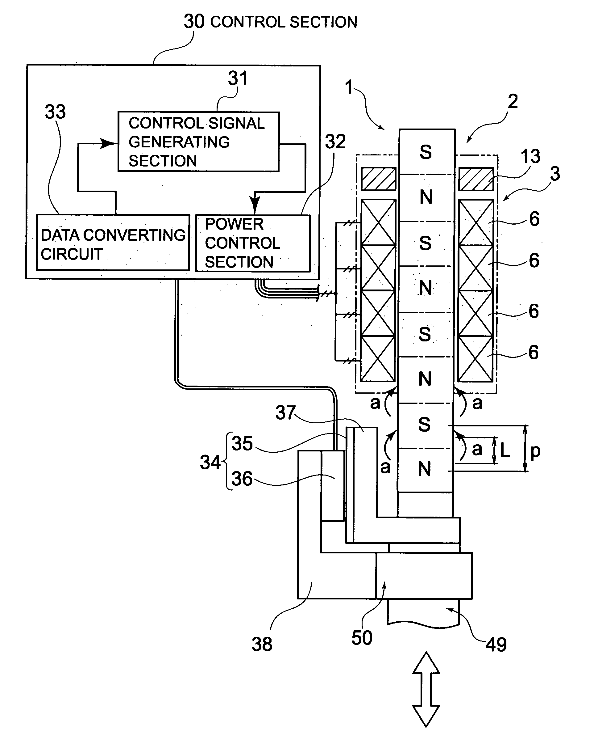
[0019] The present linear motor device comprises a linear motor 1 and a control section 30 that controls the linear motor 1.

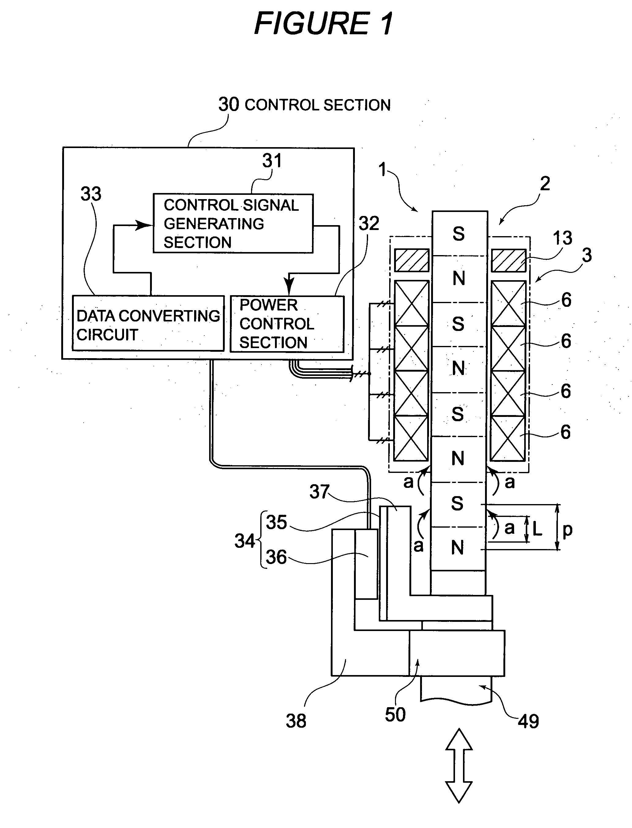
[0020] The linear motor 1 comprises a magnet member 2 composed of permanent magnets having respective N poles and S poles alternately arranged in an axial direction, and a coil member 3 which is located orthogonally to the axial direction with respect to the magnet member 2 and through which the magnet member 2 is movable in the axial direction relative to the coil member 3. Either the magnet member 2 or the coil member 3 may be a moving side. In the present embodiment, the magnet member 2 is a moving-side member, and the coil member 3 is a fixed-side member. The magnet member 2 is a round bar-like member. A magnetic flux (a) is generated between the adjacent magnetic poles N and S as shown by arrow a in FIG. 1. The coil member 3 is configured as a coil unit having ...


PUM

PropertyMeasurementUnit
attractive forceaaaaaaaaaa
thrustaaaaaaaaaa
magneticaaaaaaaaaa

Abstract

The present invention provides a linear motor device that can reduce a variation in thrust caused by a variation in attractive force. The linear motor device includes a linear motor 1 and a control section 30 that controls the linear motor 1. The linear motor 1 includes a magnet member 2 composed of permanent magnets having respective N poles and S poles alternately arranged in an axial direction, and a coil member 3 which is located orthogonally to the axial direction with respect to the magnet member 2 and through which the magnet member 2 is movable in the axial direction relative to the coil member 3. The control section 30 controls current conducted through the coil member 3 so that a moving one of the magnet member 2 and the coil member 3 reciprocates within a use range L corresponding to a part of a pitch p between the magnetic poles N and S in the magnet member 2.

Description

FIELD OF THE INVENTION [0001] The present invention relates to a linear motor device and a machine tool such as a press machine in which the linear motor device is mounted. BACKGROUND OF THE INVENTION [0002] A conventionally proposed linear motor comprises a magnet member composed of round-shaft-like permanent magnets having alternately arranged respective N poles and S poles, and a coil member having a plurality of coils arranged in an axial direction so as to surround the periphery of the magnet member (for example, the Unexamined Japanese Patent Application Publication (Tokkai-Hei) No. 10-313566). [0003] The linear motor disclosed in the Unexamined Japanese Patent Application Publication (Tokkai-Hei) No. 10-313566 is used, for example, in OA equipment or the like in place of a combination of a rotary motor and a ball screw. However, using the linear motor in a machine tool such as a press machine which makes direct-acting motion also results in a simple configuration and enhanced...

Claims


Application Information

Patent Timeline
Patent Type & Authority Applications(United States)
IPC IPC(8): H02K41/03B21D28/34
CPCB30B1/42H02K7/106H02K2213/03H02K41/031H02K7/1185H02K11/0015H02K11/21Y10T83/9476H02K41/02
Inventor OKADA, TAKUYAISHIYAMA, NORITAKA
Owner MURATA MASCH LTD
Why Eureka
Try Eureka