Light emitting device and control method thereof

a light emitting device and light control technology, applied in the direction of static indicating devices, instruments, semiconductor lamp usage, etc., can solve the problems of increasing the cost of controllers, and the cost of achieving the object of the prior art is very high, so as to reduce the number of elements and reduce the cost

Inactive Publication Date: 2008-04-03
GIGNO TECH CO LTD
View PDF2 Cites 5 Cited by
  • Summary
  • Abstract
  • Description
  • Claims
  • Application Information

AI Technical Summary

Benefits of technology

[0014] As mentioned above, the optical sensing-control unit receives the light of the light emitting unit and thus generates the leakage current to consume or adjust the electrical energy stored in the energy storage unit in the light emitting device and the control method thereof according to the invention. In addition, the light emitting unit is powered off after the electrical energy is completely consumed. Thus, it is possible to determine the light emitting time of the light emitting unit to control the total light emitting energy of the light emitting unit according to the electrical energy stored in the energy storage unit. In addition, the modularized integrated circuit can effectively decrease the number of elements and thus decrease the cost. In addition, the optical sensing-control unit has an optical sensing element, which can generate optical current when receiving the light emitted by the light emitting unit. Thus, the optical sensing-control unit can be used to adjust the electrical energy store...

Problems solved by technology

However, the color properties of light emitted by a cathode fluorescent lamp are inferior to that of the LED (Light Emitting Diode).
When the number of the LEDs of the backlight module is increased or the LEDs ...

Method used


Image

  • Light emitting device and control method thereof
  • Light emitting device and control method thereof
  • Light emitting device and control method thereof

Examples


first embodiment

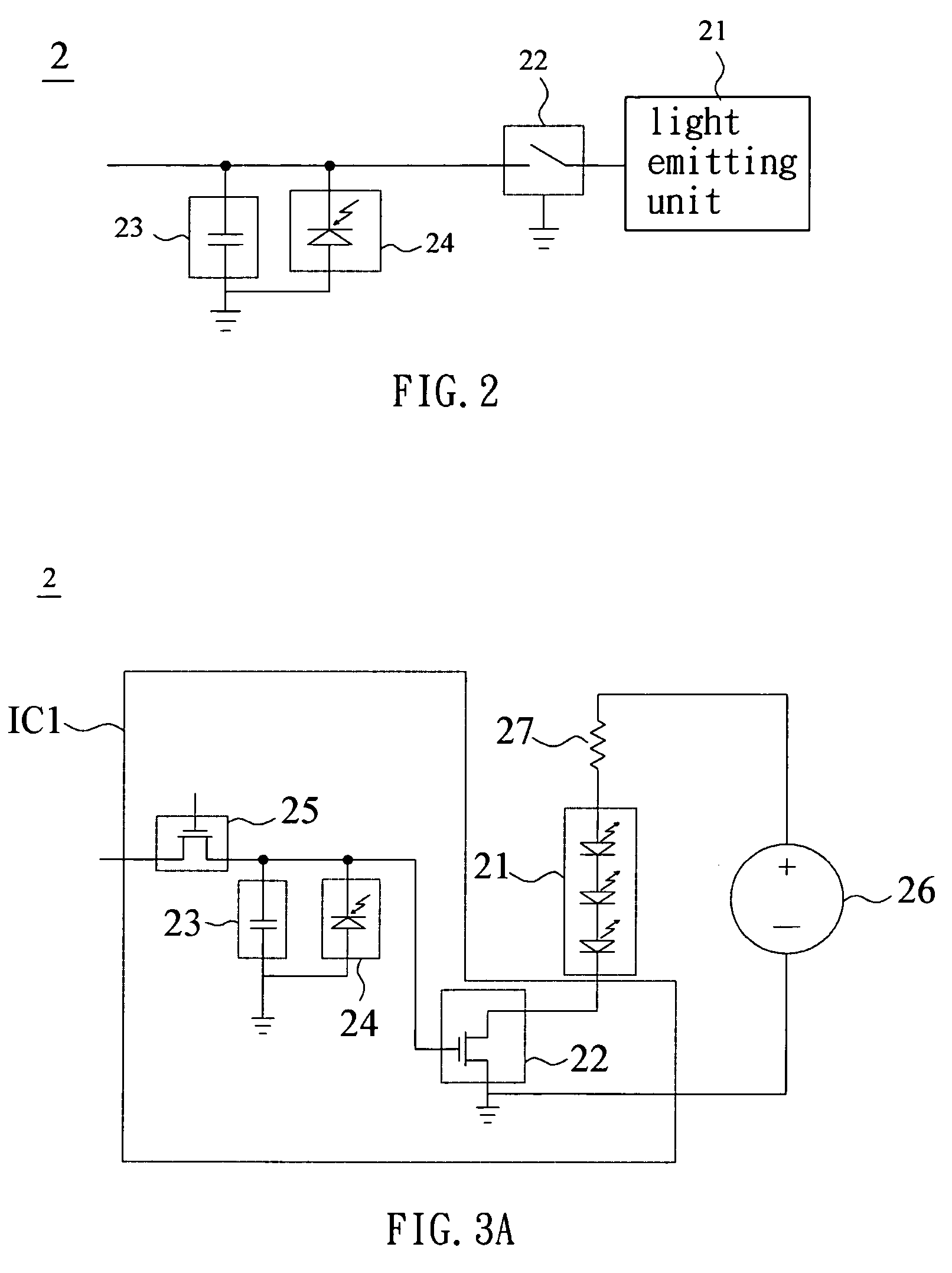
[0037] Referring to FIG. 2, a light emitting device 2 according to the first embodiment of the invention includes at least one light emitting unit 21, a first switching unit 22, an energy storage unit 23 and an optical sensing-control unit 24.

[0038] The light emitting unit 21 may include a cold cathode fluorescent lamp, a hot cathode fluorescent lamp or a LED (Light Emitting Diode). In this embodiment, the light emitting unit 21 is a LED, such as a white-light LED, a red LED, a green LED or a blue LED.

[0039] The first switching unit 22 is electrically connected to the light emitting unit 21. The first switching unit 22 may include a bipolar junction transistor (BJT) or a field effect transistor (FET). In this embodiment, the first switching unit 22 is a MOS (Metal Oxide Semiconductor) FET.

[0040] The energy storage unit 23 is electrically connected to the first switching unit 22 and stores an electrical energy. In this embodiment, the energy storage unit 23 is, for example, a char...

second embodiment

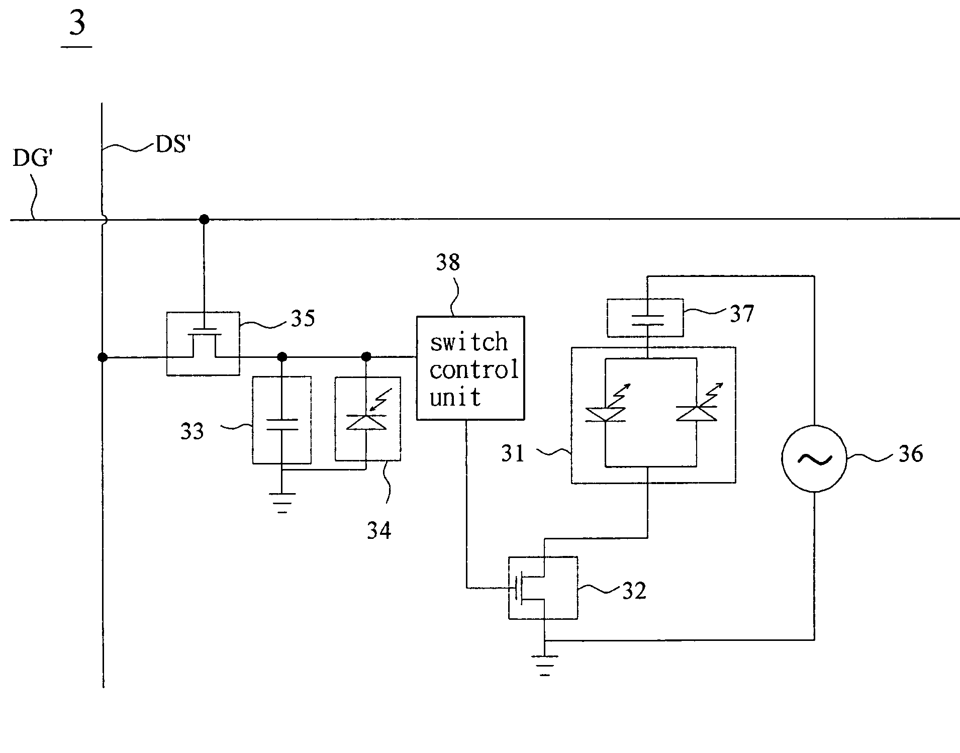
[0062] Referring to FIG. 8, a light emitting device 3 according to a second embodiment of the invention includes a light emitting unit 31, a first switching unit 32, an energy storage unit 33, an optical sensing-control unit 34, a second switching unit 35, a power supply unit 36, a current-limiting unit 37, a switch control unit 38, a row driving circuit DG′ and a column driving circuit DS′.

[0063] The energy storage unit 33, the optical sensing-control unit 34, the second switching unit 35, the switch control unit 38, the row driving circuit DG′ and the column driving circuit DS′ have the same structures and functions as those of the energy storage unit 23, the optical sensing-control unit 24, the second switching unit 25, the switch control unit 28, the row driving circuit DG and the column driving circuit DS according to the first embodiment of the invention, so detailed descriptions thereof will be omitted.

[0064] It is also of note that at least two of the light emitting unit 3...

third embodiment

[0067] With reference to FIG. 11A, a light emitting device 4 according to a third embodiment of the invention is different from that of the previously mentioned embodiments in that: the switch control unit 48 includes a comparator and the optical sensing-control unit 44 includes an optical sensing circuit 441, which senses the light emitting energy of the light emitting unit 41. Then, the optical sensing-control unit 44 adjusts the electrical energy and a corresponding voltage V1. In addition, when the optical sensing circuit 441 is not illuminated by the light emitted from the light emitting unit 41, it also senses the environment temperature so as to generate a background dark current and thus consumes the electrical energy and the corresponding voltage V1. Then, the switch control unit 48 compares the voltage V1 with a threshold voltage V2, and the switching unit 42 controls the light emitting unit 41 according to the comparing result.

[0068] In the embodiment, the threshold volt...


PUM


Abstract

A light emitting device includes at least one light emitting unit, a first switching unit, an energy storage unit and an optical sensing-control unit. The first switching unit is electrically connected to the light emitting unit. The energy storage unit is electrically connected to the first switching unit and stores electrical energy. The optical sensing-control unit electrically connected to the energy storage unit senses a light emitting energy of the light emitting unit and adjusts the electrical energy according to the light emitting energy. The first switching unit turns on and off according to the electrical energy so as to control the light emitting unit.

Description

CROSS REFERENCE TO RELATED APPLICATIONS [0001] This Non-provisional application claims priority under 35 U.S.C. §119(a) on Patent Application No(s). 095136575, 096120199 and 096135248 filed in Taiwan, Republic of China on Oct. 2, 2006, Jun. 5, 2007, and Sep. 21, 2007, the entire contents of which are hereby incorporated by references. BACKGROUND OF THE INVENTION [0002] 1. Field of Invention [0003] The invention relates to a light emitting device and a control method thereof, and, in particular, to a light emitting device possessing a self-feedback function and a control method thereof. [0004] 2. Related Art [0005] In a LCD (Liquid Crystal Display) apparatus, a cathode fluorescent lamp typically serves as a light emitting unit of a backlight module. However, the color properties of light emitted by a cathode fluorescent lamp are inferior to that of the LED (Light Emitting Diode). So, some manufacturers have used the LEDs as the light emitting devices of the backlight module of the LC...

Claims


Application Information

Patent Timeline
IPC IPC(8): H05B41/36H01L33/00H05B37/02
CPCG09G3/3426G09G3/3611G09G2360/145Y02B20/346H05B33/0821H05B33/0851H05B33/0818H05B45/12H05B45/3725H05B45/40Y02B20/30
Inventor SAH, WEN-JYH
Owner GIGNO TECH CO LTD
Why Eureka
Try Eureka