Wireless sensor device
a sensor device and wireless technology, applied in the direction of near-field systems using receivers, semiconductor/solid-state device details, instruments, etc., can solve the problems of battery not being replaced easily, device not effective in constantly acquiring physical information,
- Summary
- Abstract
- Description
- Claims
- Application Information
AI Technical Summary
Benefits of technology
Problems solved by technology
Method used
Image

Examples
embodiment mode 1
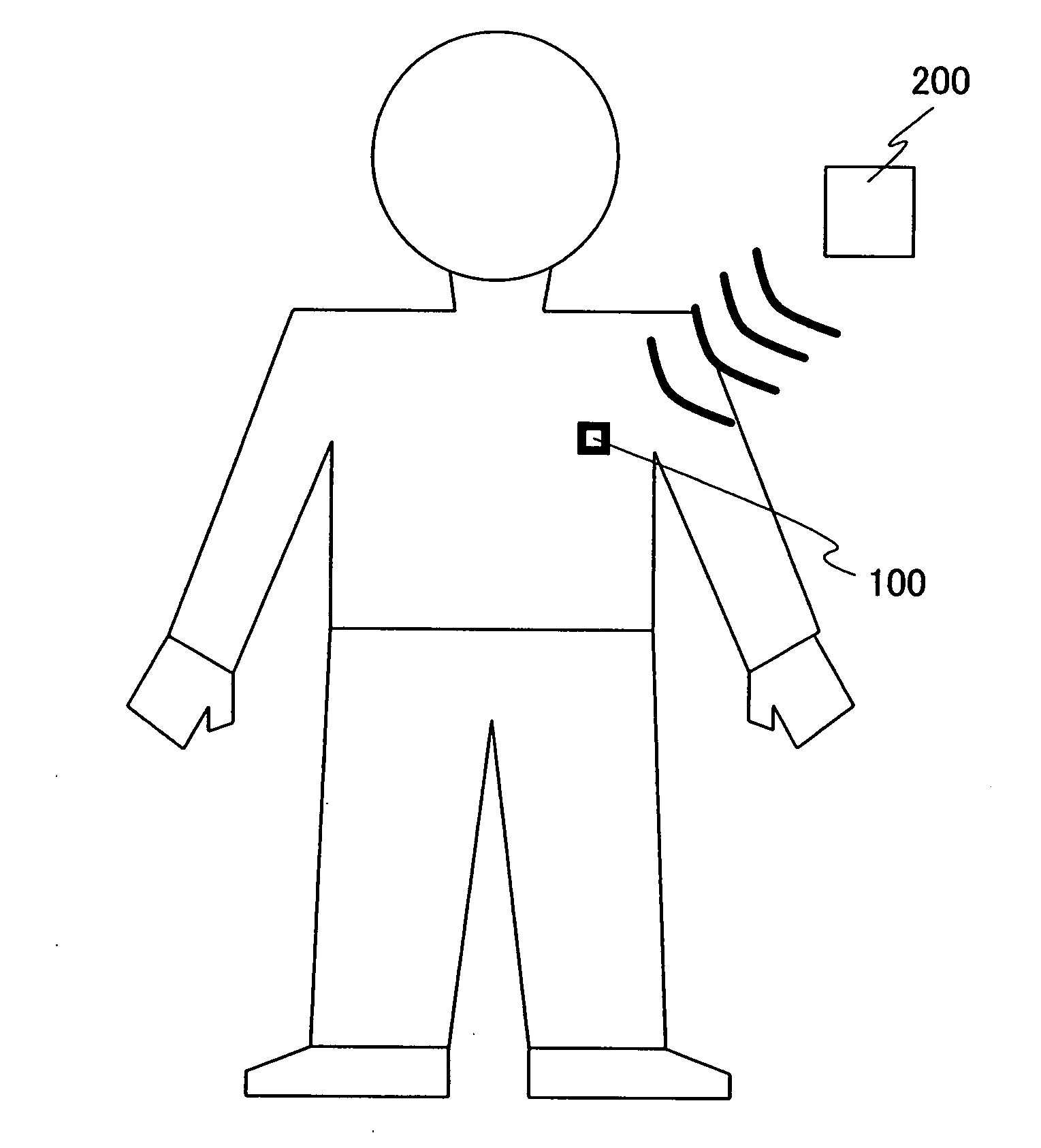
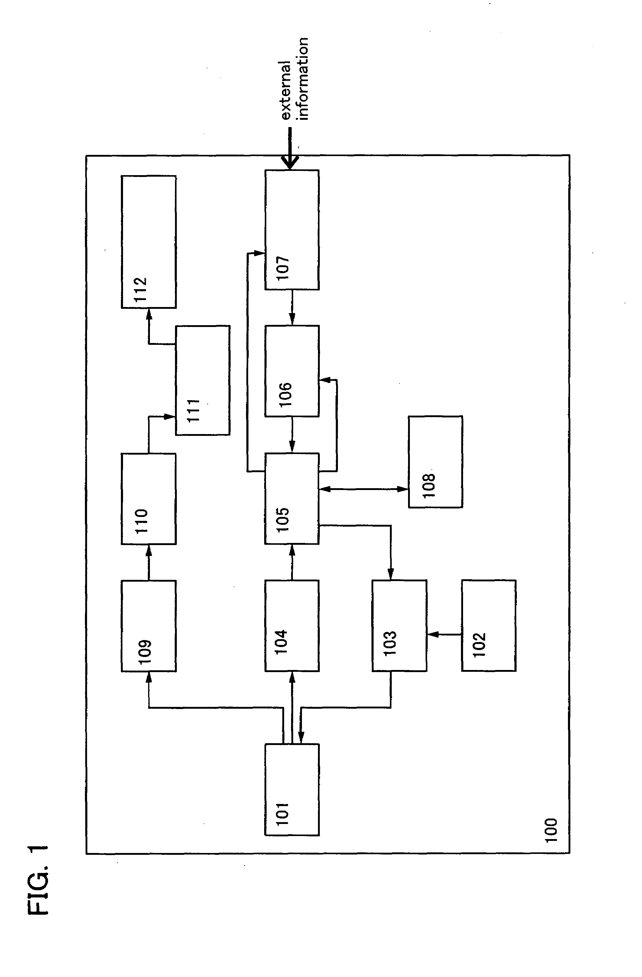
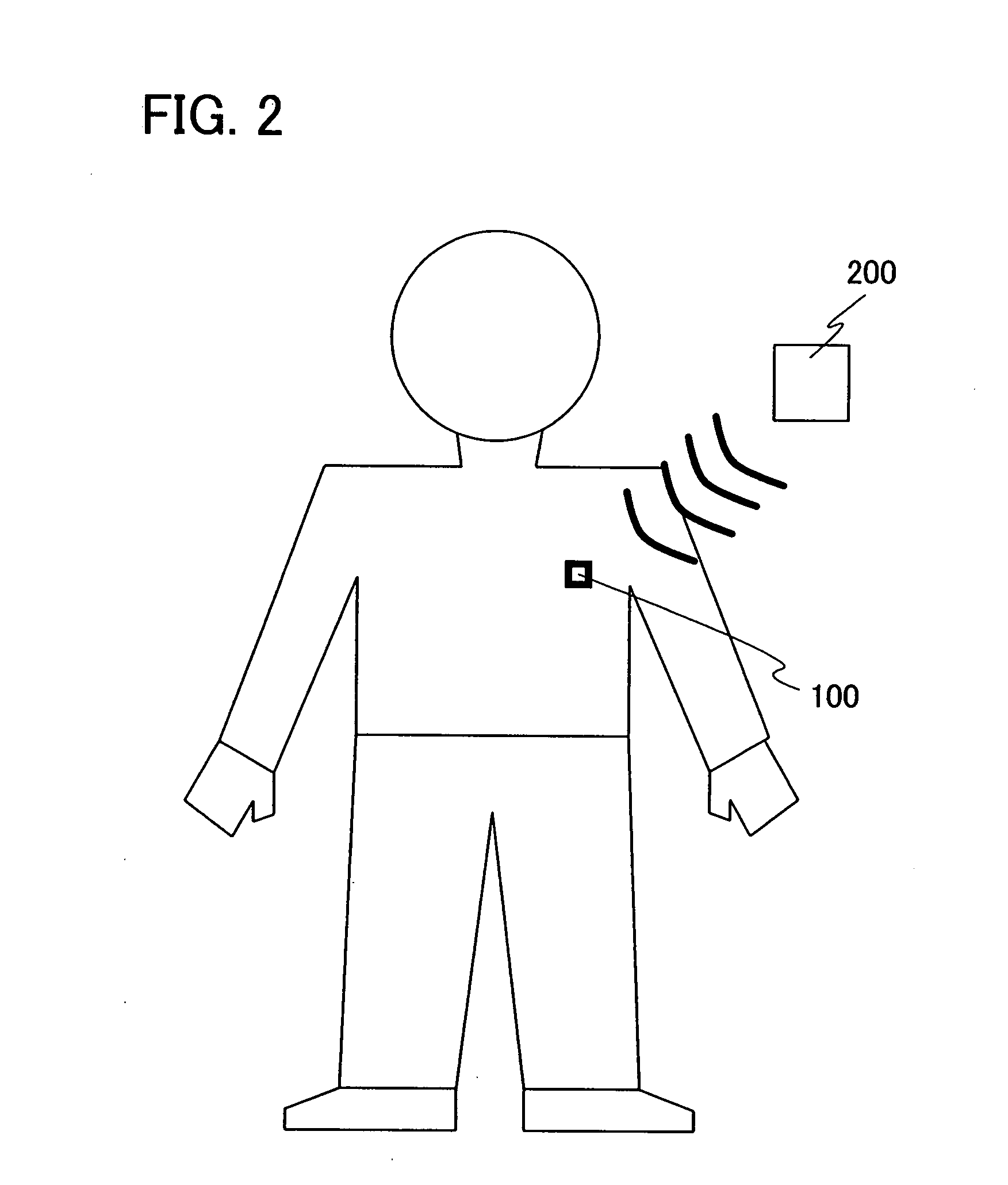
[0049]Embodiment Mode 1 of the invention is shown in FIG. 1. FIG. 1 illustrates a block diagram of the invention. A wireless sensor device 100 includes an antenna circuit 101, an oscillation circuit 102, a modulation circuit 103, a demodulation circuit 104, a logic circuit 105, an AD converter circuit 106, a sensor circuit 107, a memory circuit 108, a rectifier circuit 109, a charging circuit 110, a battery 111, and a stabilizing power supply circuit 112.
[0050]In the case of performing communication with a magnetic field, the antenna circuit 101 includes, as shown in FIG. 3A, a coiled antenna 301 and a tuning capacitor 302. The rectifier circuit 109 includes, as shown in FIG. 3B, a diode 303, a diode 304, and a smoothing capacitor 305. However, the configurations of the antenna circuit 101 and the rectifier circuit 109 are not limited to them. In the case of performing communication with not a magnetic field but an electric field, the antenna does not need to be in a coiled form.
[00...
embodiment mode 2
[0061]Embodiment Mode 2 of the invention is shown in FIG. 4. FIG. 4 illustrates a block diagram of the invention. A wireless sensor device 400 includes antenna circuits 401 and 402, the oscillation circuit 102, the modulation circuit 103, the demodulation circuit 104, the logic circuit 105, the AD converter circuit 106, the sensor circuit 107, the memory circuit 108, the rectifier circuit 109, the charging circuit 110, the battery 111, and the stabilizing power supply circuit 112.
[0062]In this embodiment mode, the antenna circuit 401 for reception of power and the antenna circuit 402 for reception of signals are provided, unlike Embodiment Mode 1. When a plurality of antenna circuits having different functions are selectively used in this manner, power transmission and signal transmission can be conducted by using different radio frequencies. For example, power transmission can be conducted with radio waves having a frequency of 13.56 MHz by utilizing a magnetic field, while signal ...
embodiment mode 3
[0069]Embodiment Mode 3 of the invention is shown in FIG. 5. FIG. 5 illustrates a block diagram of the invention. A wireless sensor device 500 includes the antenna circuit 101, the oscillation circuit 102, the modulation circuit 103, the demodulation circuit 104, the logic circuit 105, the AD converter circuit 106, the memory circuit 108, the rectifier circuit 109, the charging circuit 110, the battery 111, the stabilizing power supply circuit 112, a CCD 501, and an LED 502.
[0070]In this embodiment mode, the wireless sensor device 500 includes the LED 502 and the CCD 501, so that light emitted from the LED 502 illuminates inside of the body and the CCD 501 shoots an image of the illuminated object. A light-emission source is not limited to the LED and other types of light emitter such as an EL element can also be used. In addition, the image pickup device is not limited to the CCD, and a CMOS sensor or the like can also be used, for example.
[0071]In the case of performing communicat...
PUM
 Abstract
Description
Claims
Application Information
 - Generate Ideas
- Intellectual Property
- Life Sciences
- Materials
- Tech Scout
- Unparalleled Data Quality
- Higher Quality Content
- 60% Fewer Hallucinations
Browse by: Latest US Patents, China's latest patents, Technical Efficacy Thesaurus, Application Domain, Technology Topic, Popular Technical Reports.
© 2025 PatSnap. All rights reserved.Legal|Privacy policy|Modern Slavery Act Transparency Statement|Sitemap|About US| Contact US: help@patsnap.com