Optical resonator gyro and method for reducing resonance asymmetry errors

a technology of optical resonators and gyroscopes, applied in the field of gyroscopes, can solve the problems of reducing the accuracy of rotational rate measurement, false indication of rotation or inaccurate measurement of rotation rate, and polarization errors, and achieve the effect of reducing resonance asymmetry errors

Active Publication Date: 2008-04-03
HONEYWELL INT INC
View PDF8 Cites 34 Cited by
  • Summary
  • Abstract
  • Description
  • Claims
  • Application Information

AI Technical Summary

Benefits of technology

[0016]Apparatus and method are provided for determining the rotational rate of an optical gyro while reducing resonance asymmetry errors. In an exemplary embodiment, an optical gyro is provided comprising a ring resonator comprising an optical fiber coil having a hollow core and first and second ends, a first optical element, a second optical element, and a filter coupled between the first and second optical elements. The ring resonator has a predetermined optical mode. The first optical element is configured to receive an input light beam and transmit a portion of the input light beam in a counter-propagating direction of the ring resonator. The portion of the input light beam enters one

Problems solved by technology

In the RFOG, the glass material of the optical fiber may give rise to effects that shift the resonance frequencies of the CW and CCW paths and thus produce a false indication of rotation or inaccurate measurement of rotation rate.
Anomalies, stemming from the glass medium, that decrease the accuracy of the rotational rate measurement may be generated from a non-linear Kerr effect, stimulated Brillouin scattering, polarization errors, and Rayleigh backscatter errors.
These error mechanisms are also sensitive to the environment which, for example, gives rise to unwanted temperature sensitivity.
A reflective mirror may be used to circulate the counter-propagating light beams in the coil multiple times, but this typically reduces the signal-to-noise ratio from losses generated at the transition from the mirror to the coil.
Polarization-induced errors may result from fiber couplers that incidentally couple light into a second polarization mode, either from one optical fiber to an adjacent optical fiber or within the same fiber.
Polarization-induced errors may severely limit the accuracy of the RFOG because determination of the resonance centers for each of the resonance frequencies of the CW and CCW beams directly affects the rotational rate measurement.
Rayleigh backscatter errors may be a source of drift rate in a resonator gyro.
Backscattered light from the glass within the fiber or from imperfections with the fiber can interfere with the circulating light beams and cause significant drift rate errors.
The RFOG may encounter additional anomalies that decrease the accuracy of the rotational rate measurement.
Near resonance, the light circulating inside the resonator grows significantly, and thus the light in the mode-matched circulated wave similarly grows significantly and subsequently destructively interferes with the mode-matched zero-pass wave to produce the dip observed in the total mode-matched reflected wave.
However, practical issues may constrain the light energy at the input to the resonator from being substantially in the mode-matched state.
For example, some

Method used


Image

  • Optical resonator gyro and method for reducing resonance asymmetry errors
  • Optical resonator gyro and method for reducing resonance asymmetry errors
  • Optical resonator gyro and method for reducing resonance asymmetry errors

Examples


Embodiment Construction

[0023]The following detailed description of the invention is merely exemplary in nature and is not intended to limit the invention or the application and uses of the invention. Furthermore, there is no intention to be bound by any theory presented in the preceding background of the invention or the following detailed description of the invention.

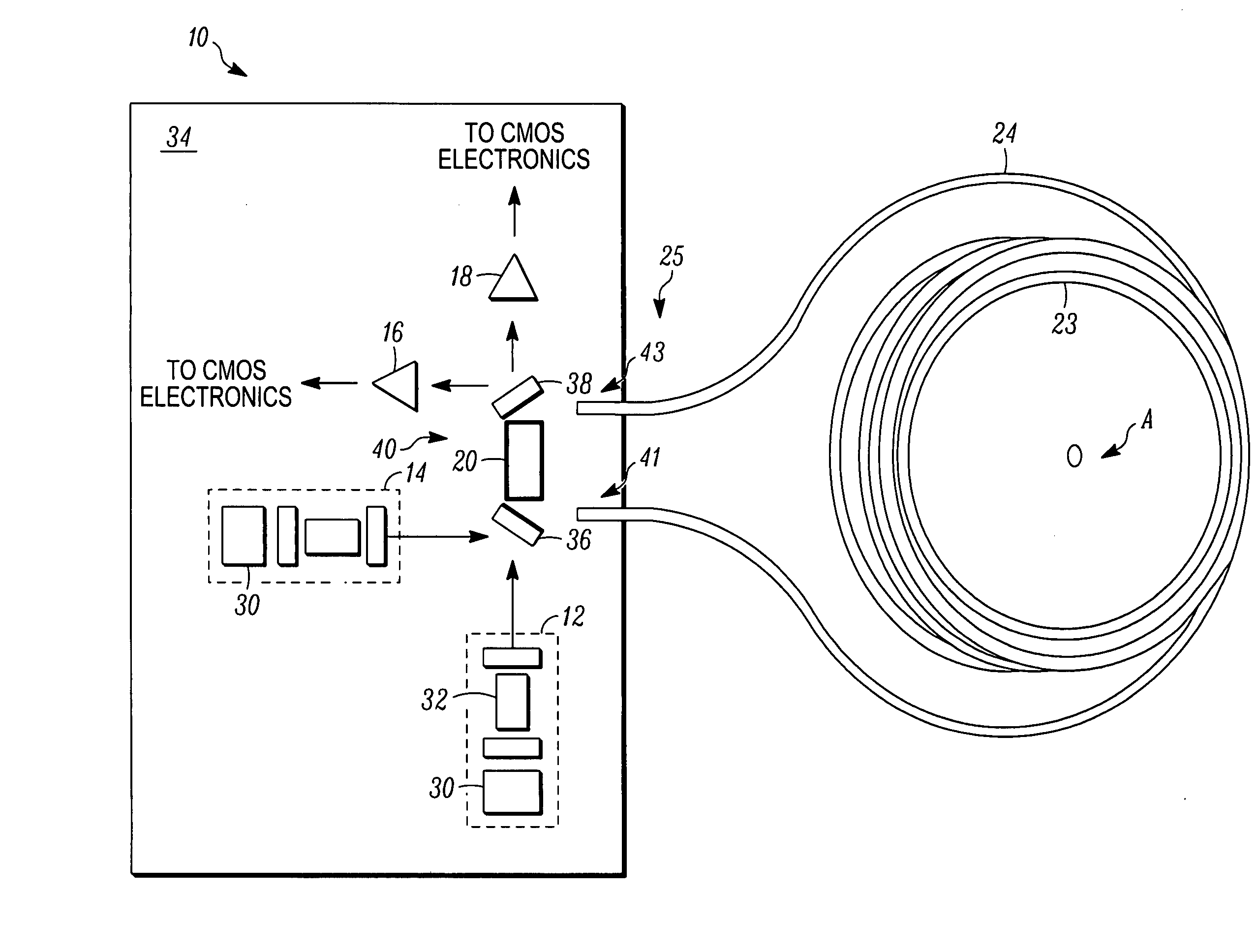
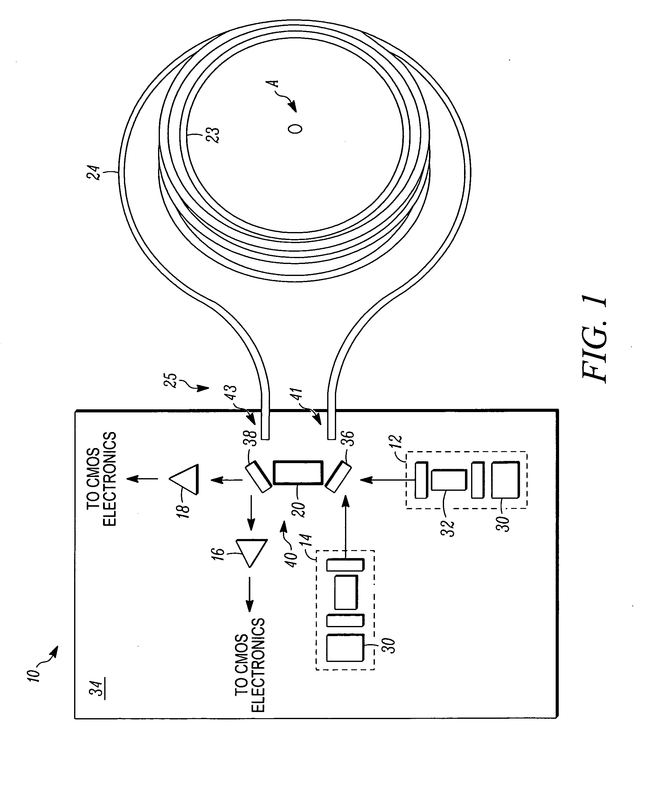
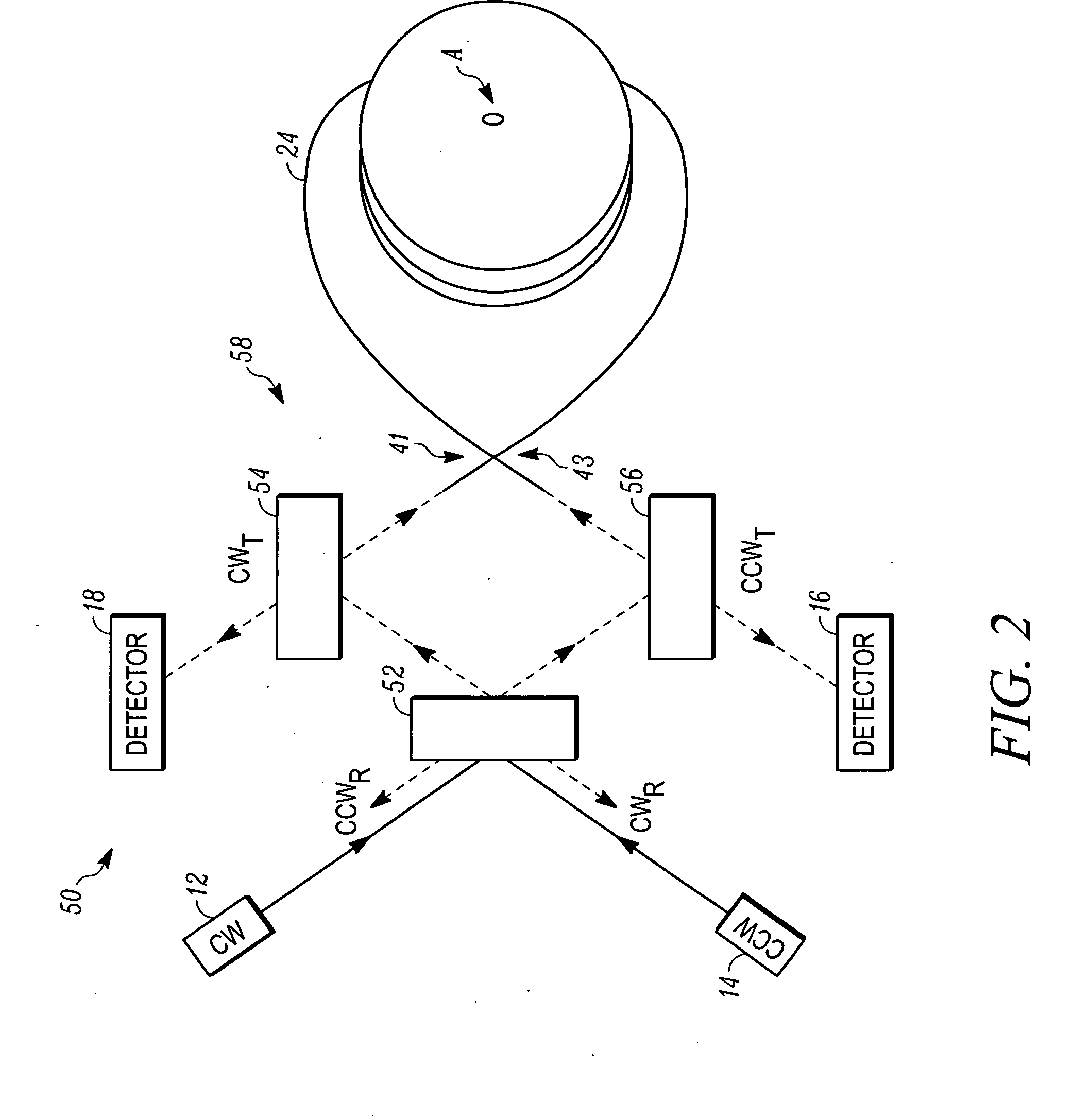
[0024]The present invention is a resonator gyro that attenuates resonance asymmetry errors and a method for operating a resonator gyro while attenuating resonance asymmetry errors that may be produced during operation of the resonator gyro. In an exemplary embodiment, the resonator gyro includes, but is not necessarily limited to, a ring resonator, one or more mirror-reflectors, and one or more photodetectors. The components of the resonator gyro are configured in a symmetric architecture to filter out (e.g., spatially filter, polarize out, and the like) stray light (e.g., non-mode-matched light) in the ring resonator in both directions (e.g...


PUM


Abstract

Methods and apparatus are provided for attenuating rotation rate errors in a resonator gyro. The gyro includes a ring resonator having a hollow core optical fiber coil and optical elements that are selected and/or oriented to reduce stray light that may be present in input light beams introduced to the ring resonator. The resonator has a predetermined mode. One of the optical elements partially transmits a portion of the input light beam to a first end of the fiber coil while partially transmitting a portion of the input light beam to a filter. Light having the predetermined mode is accepted into the first end of the fiber coil, and the filter accepts light of the input light beam having a corresponding mode. Transmission components of the circulating light beams indicates resonance peaks of the counter-propagating directions of the ring resonator.

Description

FIELD OF THE INVENTION[0001]The present invention generally relates to gyro systems, and more particularly relates to rotational sensors for use in navigation systems and attitude control.BACKGROUND OF THE INVENTION[0002]Gyros have been used to measure rotation rates or changes in angular velocity about an axis of rotation. A basic conventional fiber optic gyro (FOG) includes a light source, a beam generating device, and a coil of optical fiber coupled to the beam generating device that encircles an area. The beam generating device transmits light beams into the coil that propagate in a clockwise (CW) direction and a counter-clockwise (CCW) direction along the core of the optical fiber. Many FOGs utilize glass-based optical fibers that conduct light along a solid glass core of the fiber. The two counter-propagating (e.g., CW and CCW) beams experience different pathlengths while propagating around a rotating closed optical path, and the difference in the two pathlengths is proportion...

Claims


Application Information

Patent Timeline
IPC IPC(8): G01C19/72
CPCG01C19/727
Inventor SANDERS, GLEN A.STRANDJORD, LEE K.QIU, TIEQUN
Owner HONEYWELL INT INC
Why Eureka
Try Eureka