Synchronous rectification switching regulator, control circuit for synchronous rectification switching regulator, and control method for same

a technology of synchronous rectification switching and control circuit, which is applied in the direction of process and machine control, pulse technique, instruments, etc., can solve the problems of reducing efficiency and increasing the electricity loss caused by parasite diodes, and achieve the effect of improving efficiency

Inactive Publication Date: 2008-04-03
RICOH ELECTRONIC DEVICES CO LTD
View PDF13 Cites 37 Cited by
  • Summary
  • Abstract
  • Description
  • Claims
  • Application Information

AI Technical Summary

Benefits of technology

[0014]Various embodiments disclosed herein describe a control circuit for a synchronou...

Problems solved by technology

However, in the case of the synchronous rectification switching regulator, electric current tends to flow in reverse (backflow current) in the inductor ...

Method used


Image

  • Synchronous rectification switching regulator, control circuit for synchronous rectification switching regulator, and control method for same
  • Synchronous rectification switching regulator, control circuit for synchronous rectification switching regulator, and control method for same
  • Synchronous rectification switching regulator, control circuit for synchronous rectification switching regulator, and control method for same

Examples


Embodiment Construction

[0033]In describing example embodiments illustrated in the drawings, specific terminology is employed for the sake of clarity. However, the disclosure of this patent specification is not intended to be limited to the specific terminology so selected, and it is therefore to be understood that each specific element includes all technical equivalents that operate in a similar manner.

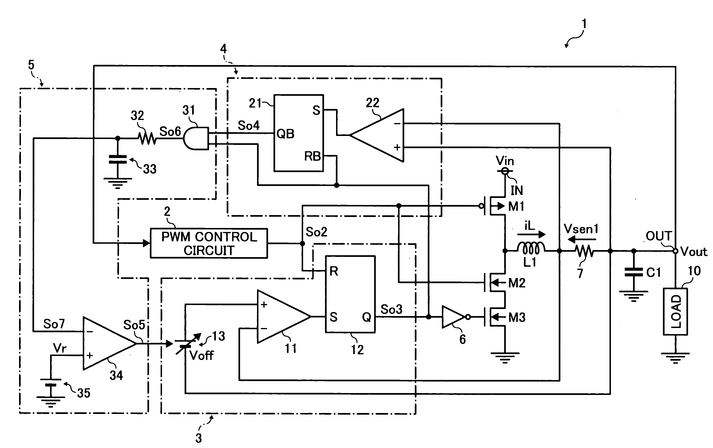
[0034]Referring now to the drawings, wherein like reference numerals designate identical or corresponding parts throughout the several views, and particularly to FIG. 4, an example configuration of a switching regulator 1 according to an example embodiment of the present invention is described.

[0035]The switching regulator 1 steps down an input voltage Vin input to an input terminal IN to output a predetermined or desirable constant voltage as an output voltage Vout from an output terminal OUT to a load 10.

[0036]The switching regulator 1 includes a switching transistor M1 that is a PMOS transistor and a syn...


PUM


Abstract

A control circuit for a synchronous rectification switching regulator including an output terminal, a switching transistor, an inductor, and a synchronous rectification transistor has a control part configured to control switching of the switching transistor to charge the inductor to and set a voltage output from the output terminal to a predetermined voltage, which causes the synchronous rectification transistor to switch reversely to the switching transistor and discharge the inductor, and backflow prevention part configured to block a current flowing in the synchronous rectification transistor to prevent a backflow current that flows in a direction from the output terminal to the synchronous rectification transistor. The backflow prevention part detects a forward current and regulates timing to block the current flowing in the synchronous rectification transistor and to regulate a time period from blocking the current flowing in the synchronous rectification transistor to determining that the forward current is zero.

Description

CROSS-REFERENCE TO RELATED APPLICATION[0001]This application claims priority from Japanese Patent Application No. 2006-268325, filed on Sep. 29, 2006, the disclosure of which is hereby incorporated by reference in its entirety.BACKGROUND OF THE INVENTION[0002]1. Field of the Invention[0003]The present invention relates generally to a synchronous rectification switching regulator, a control circuit for a synchronous rectification switching regulator, and a method of controlling the synchronous rectification switching regulator.[0004]2. Discussion of the Background Art[0005]In recent years, a need has arisen to extend battery life in electronic devices that use a battery for power supply (e.g., PDA or personal digital assistance, cellular phone, etc). Battery life may be extended by enhancing a power supply circuit as well as by reducing wasteful power consumption.[0006]In such electronic devices, a non-insulated switching regulator using an inductor is commonly used as an efficient p...

Claims


Application Information

Patent Timeline
IPC IPC(8): H02M7/04
CPCY02B70/1466H02M3/1588Y02B70/10H02M3/155H03K17/687
Inventor SOHMA, SHOHTAROH
Owner RICOH ELECTRONIC DEVICES CO LTD
Why Eureka
Try Eureka