Electrical submersible pump

Inactive Publication Date: 2008-04-03
WEATHERFORDLAMB
View PDF40 Cites 53 Cited by
  • Summary
  • Abstract
  • Description
  • Claims
  • Application Information

AI Technical Summary

Benefits of technology

[0019]In another embodiment still, a pump assembly comprises a pump adapted to pump a fluid between at least two fluid cavities and a rotary motor adapted to actuate the pump, wherein a direction of fluid flow between the at least two fluid cavities is r

Problems solved by technology

Many hydrocarbon wells are unable to produce at commercially viable levels without assistance in lifting formation fluids to the earth's surface.
More commonly, formation pressure is inadequate to drive fluids upward in the wellbore.
The rise of the liquid level in the casing leads to a pressure increase of the liquid in the casing, which may shut off the flow of gas unless the liquid is removed.
Submersible pump assemblies which utilize a linear electric motor face many challenges during their employment.
A first problem relates to

Method used


Image

  • Electrical submersible pump
  • Electrical submersible pump
  • Electrical submersible pump

Examples


Example

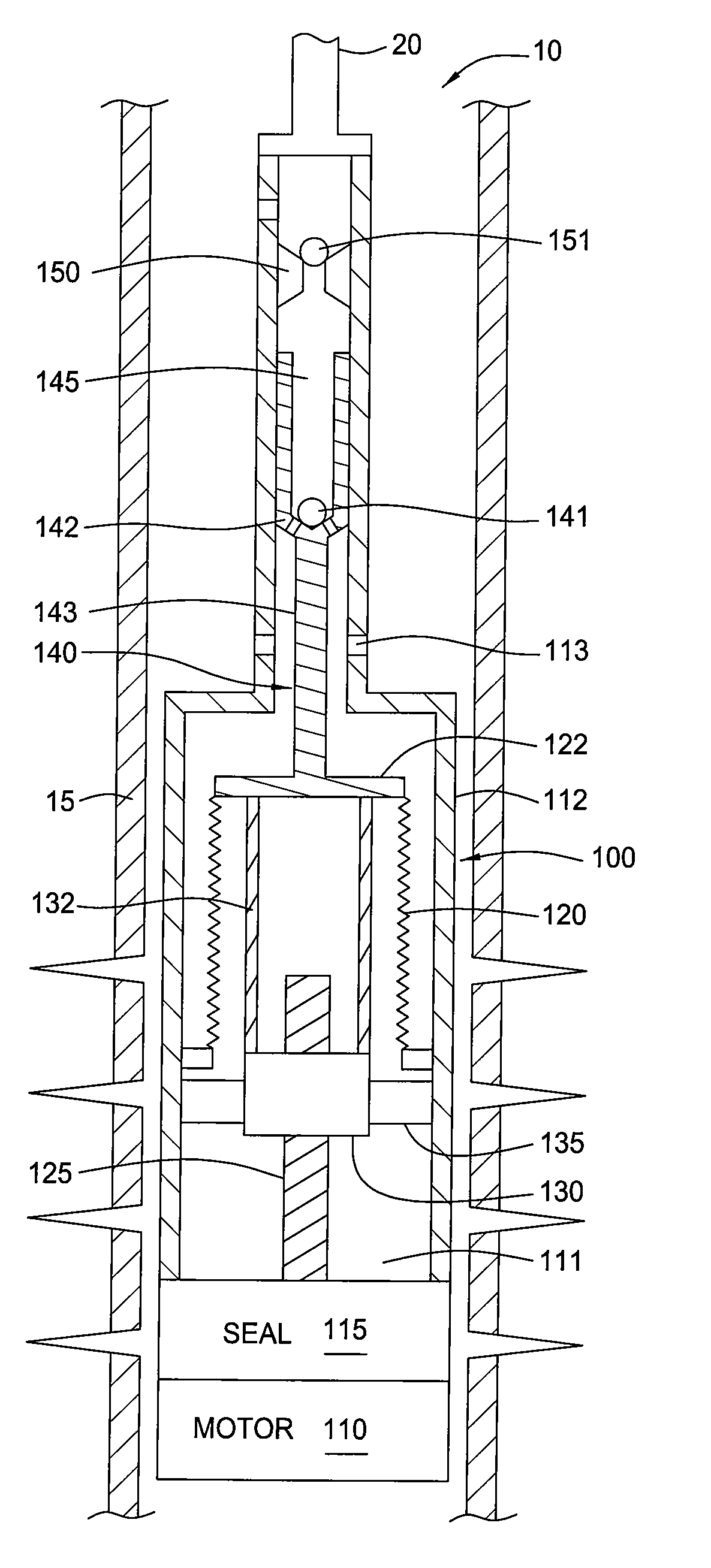
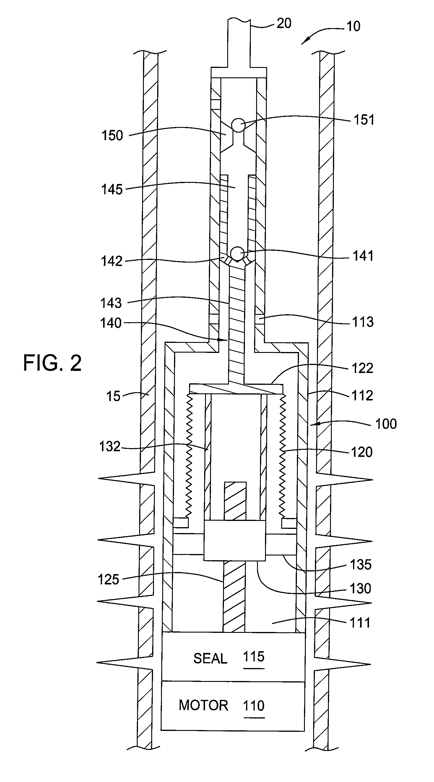
[0029]A method and apparatus for lifting fluids from a well is provided. In one embodiment, a pump assembly comprises a rotary motor adapted to actuate a reciprocating pump. The motor shaft of the rotary motor is coupled to a drive member of the reciprocating pump. In operation, rotation of the rotary motor causes reciprocation of the reciprocating pump.

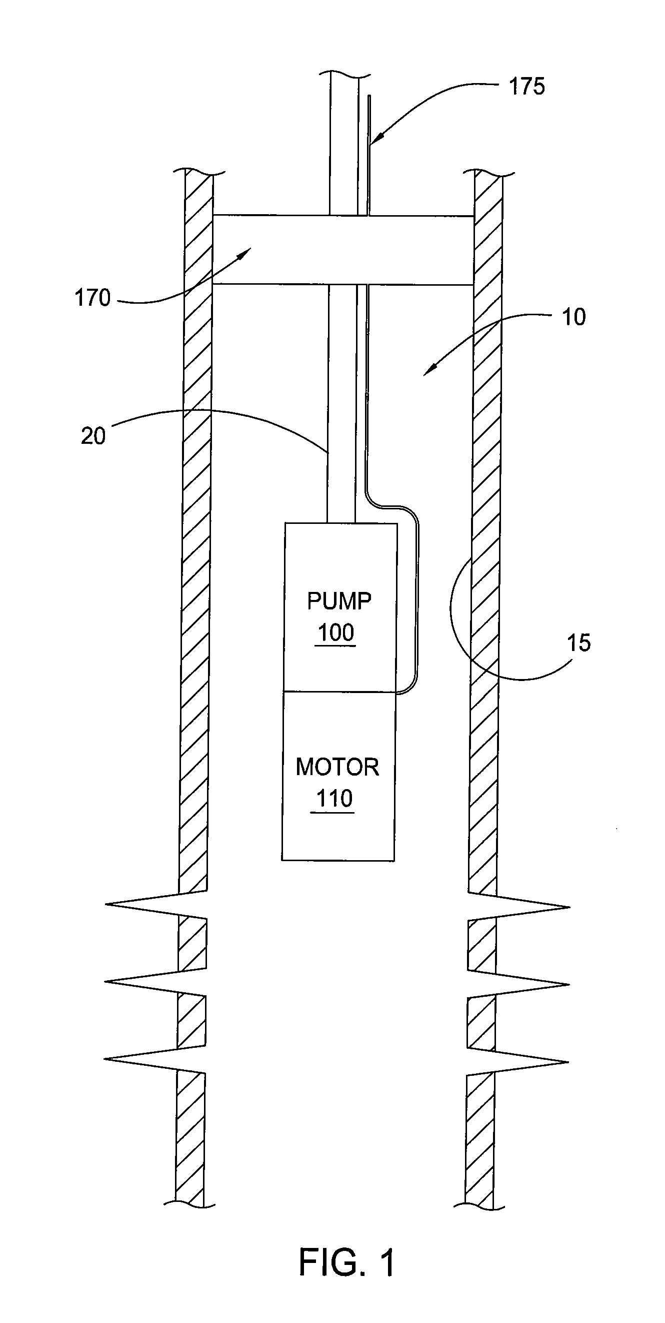
[0030]FIG. 1 is a partial cross-section view of a wellbore 10. A casing 15 is fixed in the wellbore 10 by cured cement. The casing 10 is perforated to allow the inflow of formation fluids. A string of production tubing 20 extends from the surface to a subsurface safety valve 170. The production tubing 20 then extends below the subsurface safety valve 170 to the production zone. The production tubing 20 includes an electrical submersible pump 100 disposed at its lower end. The pump 100 is being reciprocated by a submersible, rotary electrical motor 110. Preferably, the motor 110 is disposed below the pump 100 so that formation fluids ...


PUM


Abstract

A method and apparatus for lifting fluids from a well is provided. In one embodiment, a pump assembly comprises a rotary motor adapted to actuate a reciprocating pump. The motor shaft of the rotary motor is threadedly coupled to a drive member of the reciprocating pump. In operation, rotation of the rotary motor causes reciprocation of the reciprocating pump.

Description

BACKGROUND OF THE INVENTION[0001]1. Field of the Invention[0002]Embodiments of the present invention generally relate to a pumping apparatus for transporting fluids from a well formation to the earth's surface. Particularly, embodiments of the present invention relate to an electrical submersible pump assembly having a positive displacement pump driven by a rotary motor. More particularly, embodiments of the present invention relate to a pump assembly having a rotary motor capable of rotating in two directions.[0003]2. Description of the Related Art[0004]Many hydrocarbon wells are unable to produce at commercially viable levels without assistance in lifting formation fluids to the earth's surface. In some instances, high fluid viscosity inhibits fluid flow to the surface. More commonly, formation pressure is inadequate to drive fluids upward in the wellbore. In the case of deeper wells, extraordinary hydrostatic head acts downwardly against the formation, thereby inhibiting the unas...

Claims


Application Information

Patent Timeline
IPC IPC(8): F04B35/04
CPCF04B9/02F04B47/08F04B47/06F04B43/10E21B43/128F04F9/00
Inventor YURATICH, MICHAEL ANDREWKENNEDY, STEVEN CHARLES
Owner WEATHERFORDLAMB
Why Eureka
Try Eureka