File server that allows an end user to specify storage characteristics with ease

a file server and storage technology, applied in the direction of memory addressing/allocation/relocation, sustainable buildings, instruments, etc., can solve the problems of fragmentation of this used memory area, difficult to effectively reduce the power consumed by the memory only at the hardware, and hardly controlled memory power consumption, etc., to achieve the effect of substantially reducing the power consumed by the memory

Inactive Publication Date: 2008-04-03
HITACHI LTD
View PDF6 Cites 14 Cited by
  • Summary
  • Abstract
  • Description
  • Claims
  • Application Information

AI Technical Summary

Benefits of technology

[0033]According to this embodiment of the invention, the power consumed by the memory can be substantially reduced without affecting the capability of the processor to access the memory.

Problems solved by technology

On the other hand, the power consumption of the memory was hardly controlled.
In practice, therefore, it is very difficult to effectively reduce the power consumed by the memory only at the hardware level without cooperating with basic system software.
In case of which the memory is managed by the operating system, fragmentation of this used memory area is inevitable.

Method used


Image

  • File server that allows an end user to specify storage characteristics with ease
  • File server that allows an end user to specify storage characteristics with ease
  • File server that allows an end user to specify storage characteristics with ease

Examples


first embodiment

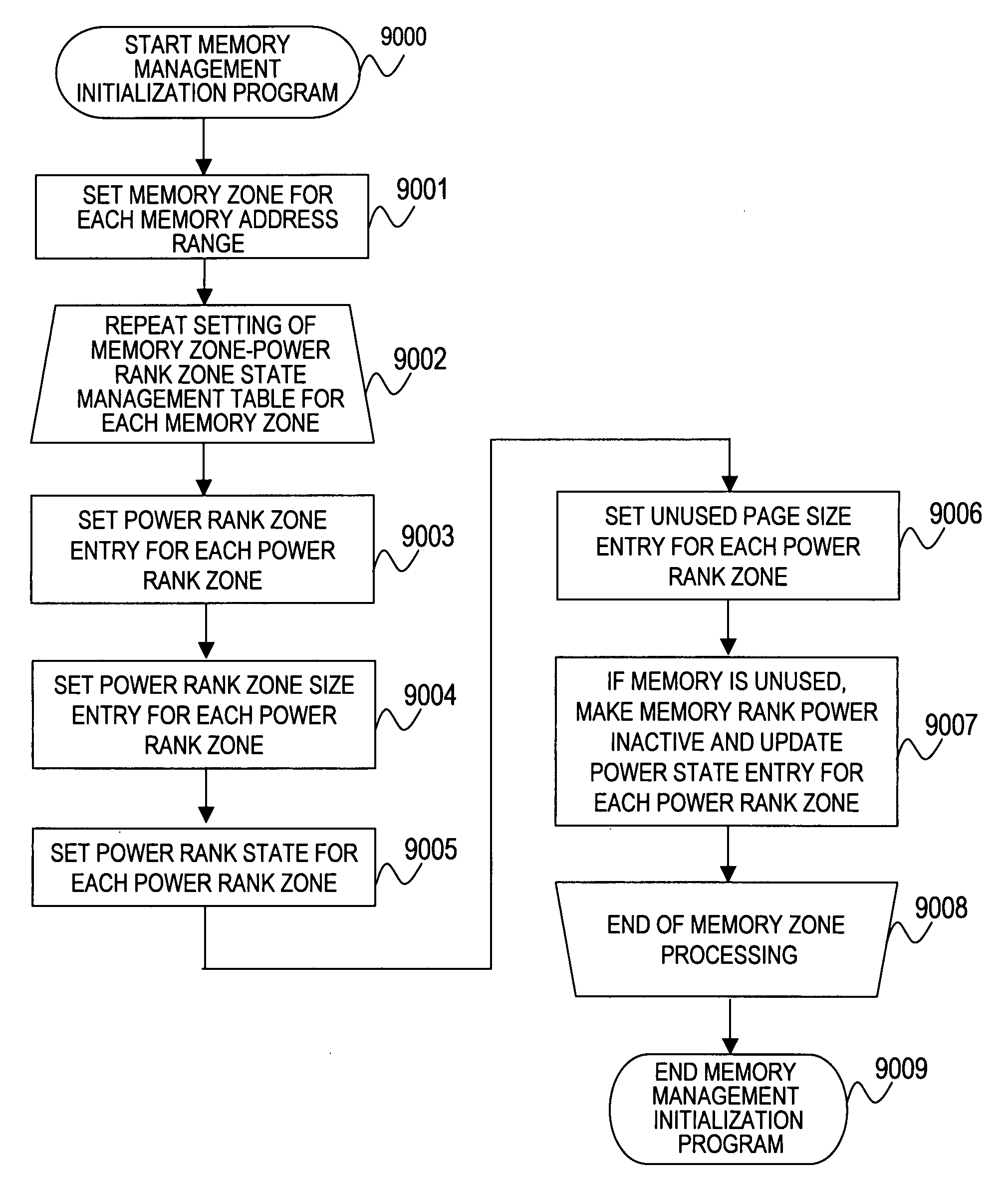
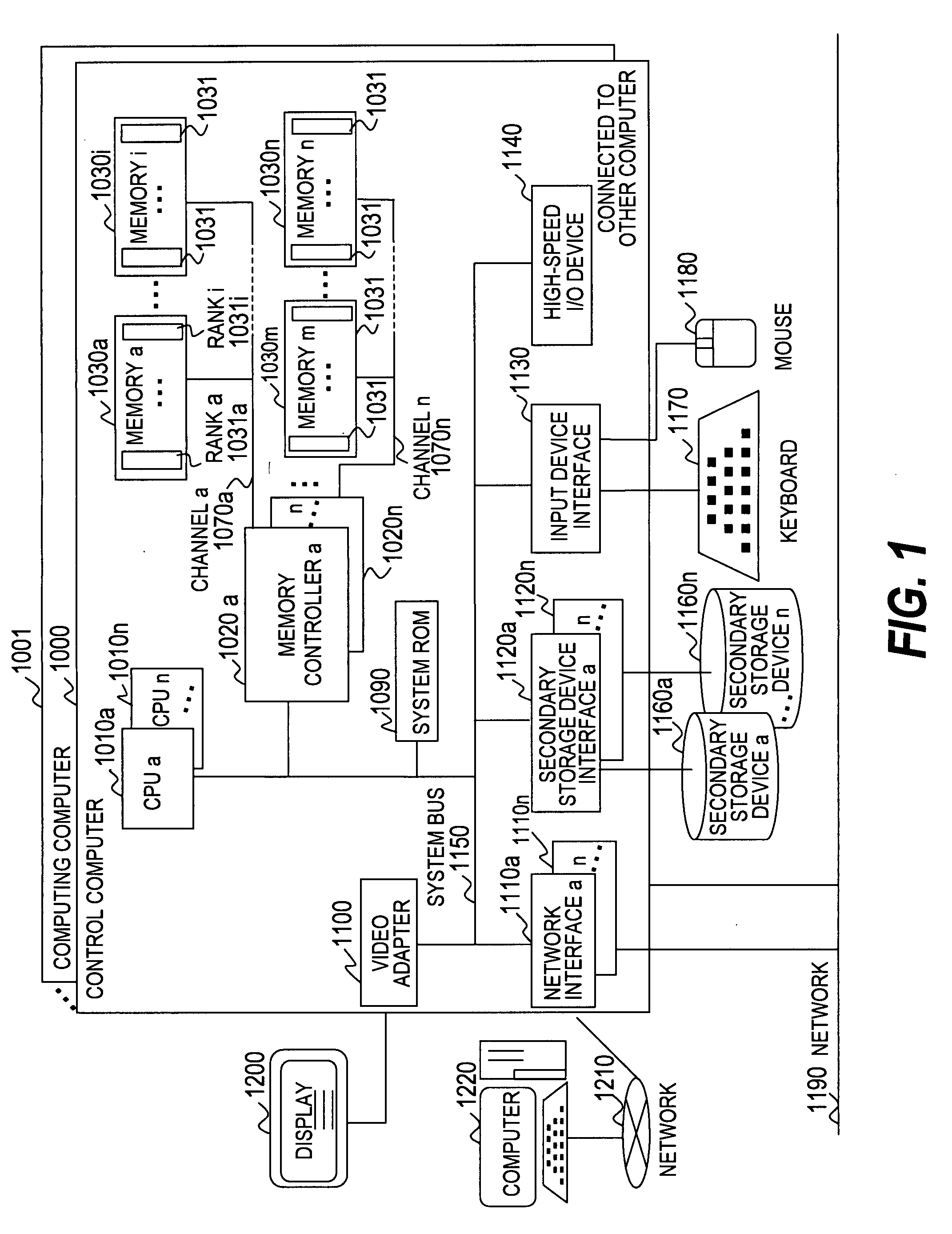
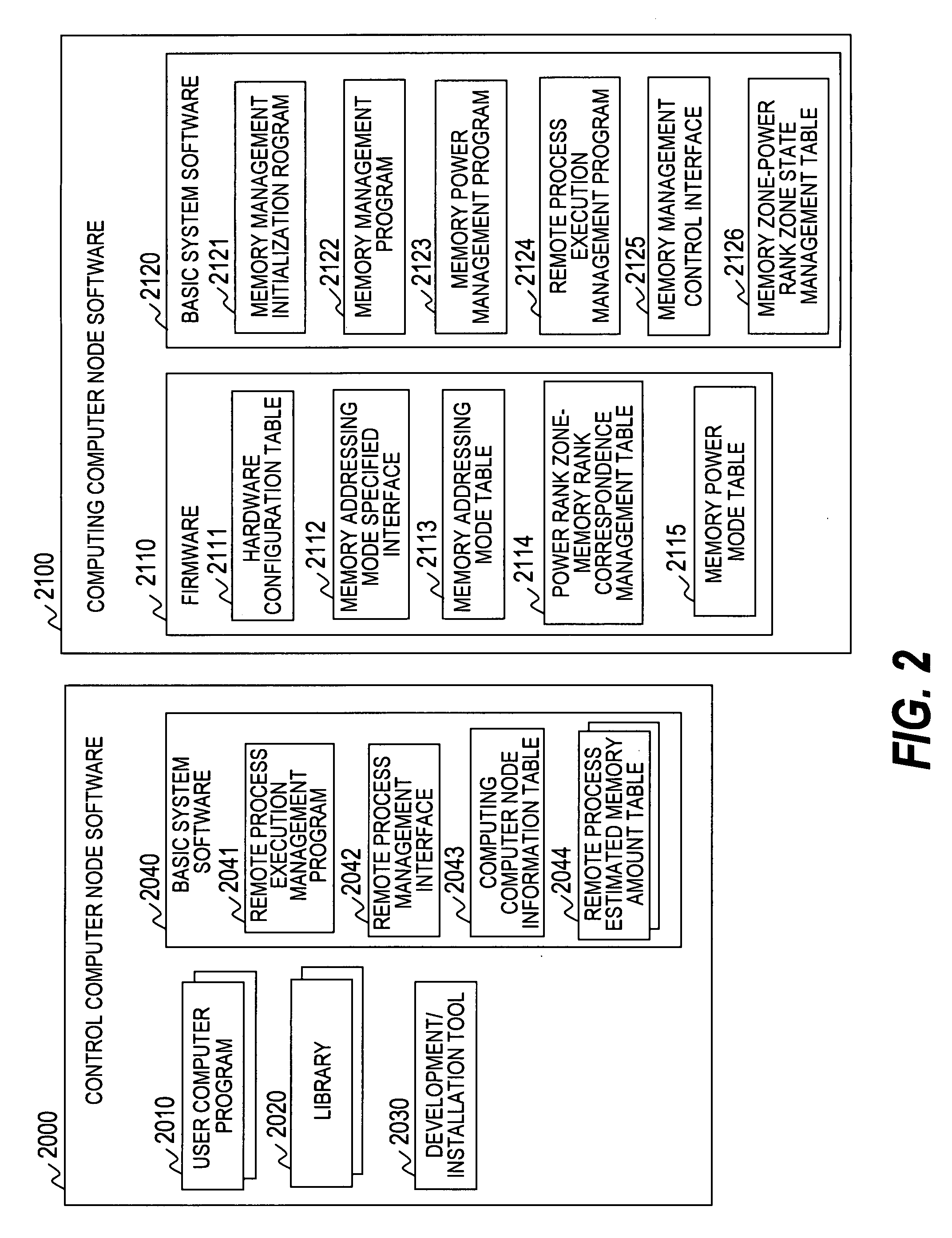
[0053]A first embodiment of the invention will now be described referring to FIGS. 1 to 14.

[0054]FIG. 1 is a drawing showing the structure of the computing system according to the first embodiment of the invention.

[0055]The computing system of the first embodiment is provided with a control computer 1000 and a computing computer 1001. Since the hardware constitutions of the control computer 1000 and the computing computer 1001 are identical, the hardware constitution of the control computer 1000 will be described as an example. The control computer 1000 comprises processors (hereafter, CPU) 1010a to 1010n (hereafter, the CPU 1010a to 1010n will be referred to collectively as CPU 1010), memory controllers 1020a to 1020n (hereafter, the memory controllers 1020a to 1020n will be referred to collectively as the memory controller 1020), memories 1030a to 1030n (hereafter, the memories 1030a to 1030n will be referred to collectively as the memory 1030), system ROM 1090, video adapter 1100...

second embodiment

[0322]A second embodiment of the invention will now be described referring to FIGS. 15 to 18.

[0323]The second embodiment is an embodiment wherein, in case of which the capacity of the memory 1030 required for the computing computer 1001 to execute a remote process is activated first, the user can specify the method of activation of the power rank zones to be activated first.

[0324]Hereafter, only those parts of the second embodiment which are different from the first embodiment will be described.

[0325]The same numerals are assigned to the same structures as in the first embodiment.

[0326]FIG. 15 is a drawing showing the structure of the basic system software 15000 stored in the control computer 1000 according to the second embodiment of the invention.

[0327]A basic system software 15000 is executed by the CPU 1010 with which the control computer node 1000 is provided.

[0328]The basic system software 15000 includes a used memory power rank policy table 15010.

[0329]The used memory power r...


PUM


Abstract

A computing node which reduces substantially and effectively reduces the power consumed by a memory is provided without affecting the efficiency whereby a processor accesses the memory. The computing node executes a user program sent by a control node. In case of which a message including the capacity of the memory required to execute a user program is received, a memory rank corresponding to the capacity of the required memory is made active by a memory controller before the user program is loaded into the memory.

Description

CLAIM OF PRIORITY[0001]The present application claims priority from Japanese patent application P2006-267843 filed on Sep. 29, 2006, the content of which is hereby incorporated by reference into this application.BACKGROUND OF THE INVENTION[0002]This invention relates to a method of memory control and process control of a computing system, and particularly to a method of reducing the power consumption of a main memory taking account of program execution and process control.[0003]In an ordinary computing system, power is consumed by the operation of the hardware with which the computing system is provided. Hardware means the processor, main memory (memory), secondary storage and Input / Output (I / O) devices, for example.[0004]In case of which a computing system consumes power in large amount, a large amount of heat is generated simultaneously. For this reason, a cooling installation for removing the heat generated by the computing system must be installed. Apart from the cost of the pow...

Claims


Application Information

Patent Timeline
Patent Type & Authority Applications(United States)
IPC IPC(8): G06F12/00
CPCG06F1/3203G06F1/3275G06F9/5044G06F9/5094Y02B60/1228G06F2212/1028Y02B60/1225Y02B60/142G06F12/06Y02D10/00
Inventor OGASAWARA, KATSUHISASUGITA, YUMIKO
Owner HITACHI LTD
Why Eureka
Try Eureka