
Roof railing assembly

a technology for railings and assemblies, applied in the direction of supplementary fittings, vehicle components, transportation and packaging, etc., can solve the problems of high corrosion of metals, high and large number of parts, so as to reduce the weight, reduce the number of parts and manufacturing steps, and reduce the total manufacturing cost of rail assemblies

Inactive Publication Date: 2008-04-10
MATHSON INDS
View PDF11 Cites 24 Cited by
  • Summary
  • Abstract
  • Description
  • Claims
  • Application Information

AI Technical Summary

Benefits of technology

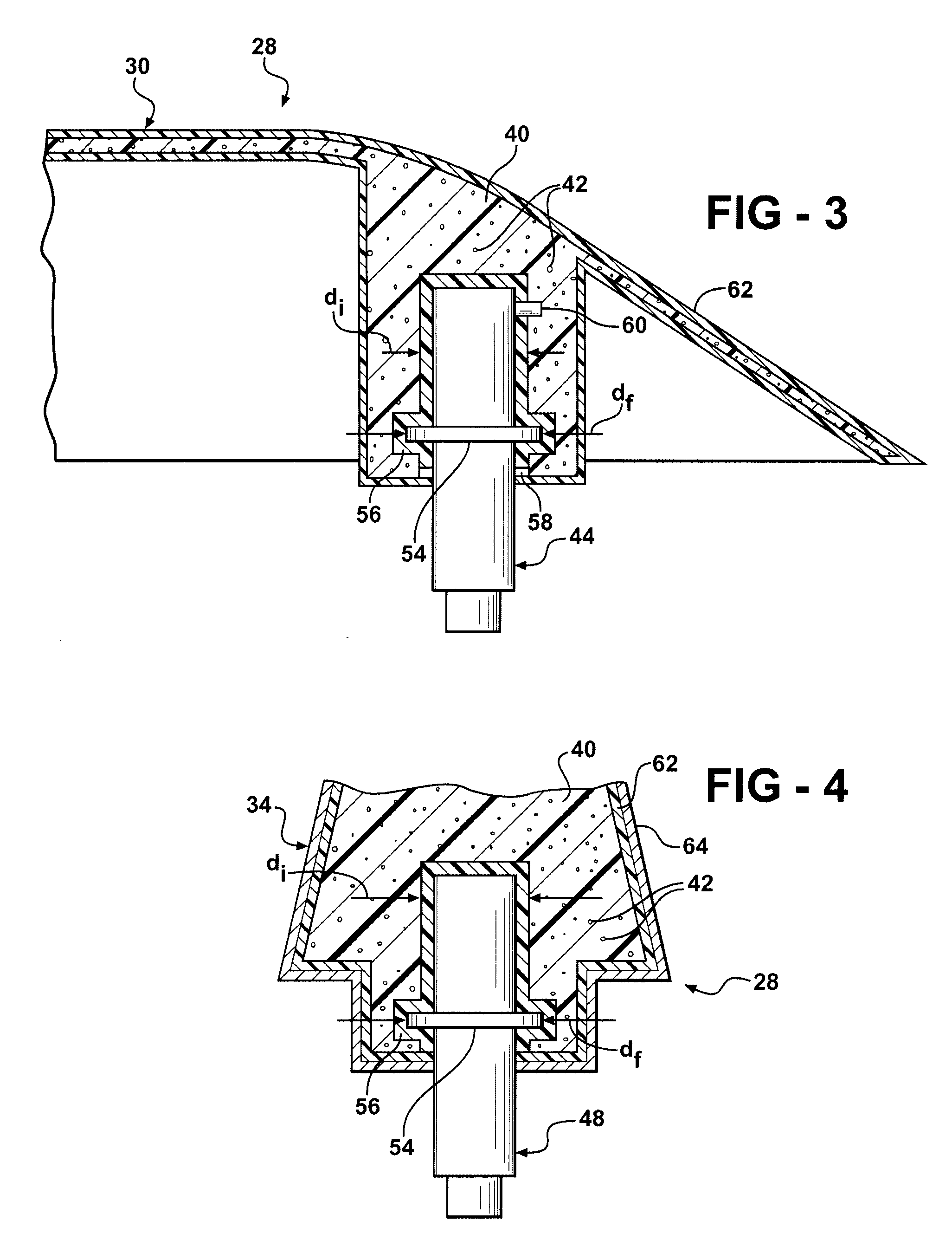
[0013]The invention also provides a roof railing assembly including a torque limited disposed about the fastener for disconnecting the fastener from the vehicle roof to avoid excessive loading on the fastener.
[0015]The invention provides an assembly having structural rigidity, dimensional stability, and outer surface quality similar to rail assemblies having metal bracket attachments, while simultaneously providing a weight reduction. Additionally, the number of parts and manufacturing steps are reduced thus decreasing the total manufacturing cost of the rail assembly. Furthermore, corrosion resistance of the rail assembly is improved and the life of tooling required to manufacture the assembly is increased.

Problems solved by technology

However, metal is highly corrosive, dense, and requires many parts.
Plastic may be used; however, due to its high coefficient of thermal expansion, injection molded plastic parts warp as they cool.
Therefore, plastic parts connected to metal parts develop sink marks and cracks due to the large difference between the coefficients of thermal expansion of each part, particularly in automotive applications where the parts are exposed to extreme temperatures.
Furthermore, plastic is less rigid than metal and therefore provides less structural support.

Method used


Image

  • Roof railing assembly
  • Roof railing assembly
  • Roof railing assembly

Examples


Embodiment Construction

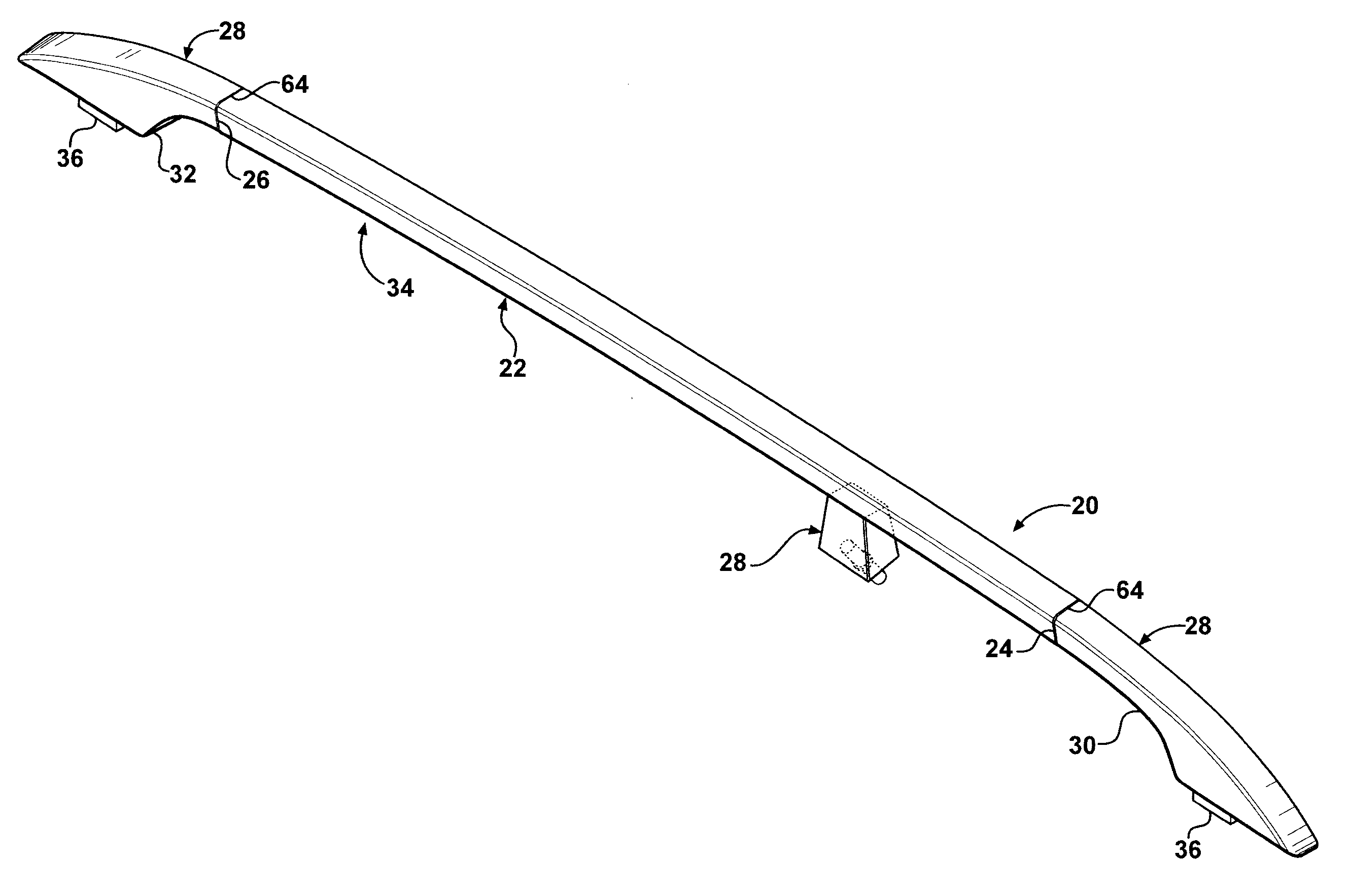
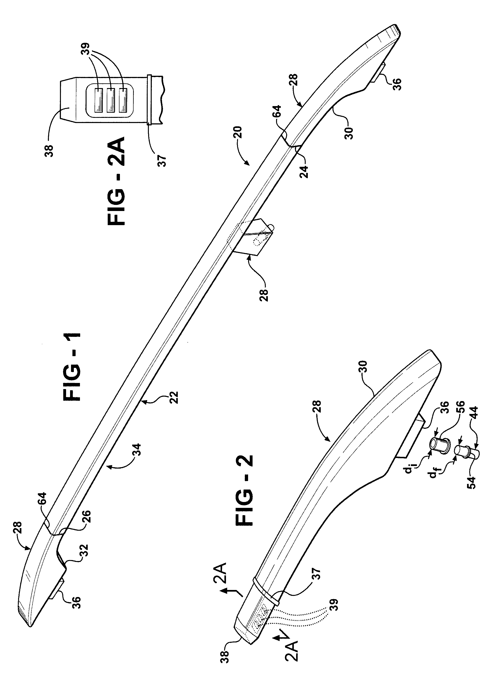
[0022]Referring to the Figures, wherein like numerals indicate corresponding parts throughout the several views, a roof railing assembly 20 for a vehicle roof (not shown) of a vehicle is generally shown.

[0023]A rail 22 is generally indicated in FIG. 1 and has a front end 24 and a rear end 26. The rail 22 is generally tubular and extends parallel to the vehicle roof. A bracket attachment 28 is generally shown and is disposed on the rail 22 for supporting the rail 22 on the vehicle roof. The bracket attachment 28 includes a front bracket attachment 30 disposed on the rail 22, a rear bracket attachment 32 disposed on the rail 22, and an intermediate bracket attachment 34 disposed on the rail 22 between the front bracket attachment 30 and the rear 20 bracket attachment 32. Each of the bracket attachments 30, 32, 34 has a mounting end 36 and a rail end 38. The mounting end 36 of each bracket attachment 30, 32, 34 is attached to the rail 22 using an adhesive such as glue. A seal 37 is dis...


PUM


Abstract

A roof railing assembly (20) includes a rail (22), a bracket attachment (28) disposed on the rail (22), and a fastener (44, 46, 48) on the bracket attachment (28), wherein the bracket attachment (28) is a defined by a structural layer of material (40) which defines a plurality of small voids (42). A flange (54) is disposed about the fastener (44, 46, 48) for restricting axial movement. An insulating layer (56) is disposed about the supported end (50) of the fastener (44, 46, 48) for absorbing force. The outer diameter of the flange (54) is greater than the outer diameter of the insulating layer (56) to further restrict axial movement. A torque limiter (58) is disposed about the fastener (44, 46, 48) for disconnecting the fastener (44, 46, 48) from the vehicle roof to avoid excessive loading on the fastener (44, 46, 48). A plurality of ribs (60) are disposed on the fastener (44, 46, 48) and extend radially outwardly into the bracket attachment (28) for restricting rotational movement of the fastener (44, 46, 48).

Description

CROSS-REFERENCE TO RELATED APPLICATIONS[0001]This application claims priority to Provisional Application 60 / 850,555, for BMW E70 ROOF RAILING ASSEMBLY, filed on Oct. 10, 2006.BACKGROUND OF THE INVENTION[0002]1. Field of the Invention[0003]A roof railing assembly for a vehicle roof of a vehicle.[0004]2. Description of the Prior Art[0005]Roof railing assemblies for motor vehicles typically include a rail having bracket attachments for supporting the rail on the vehicle roof with a fastener on each bracket attachment for securing the assembly to the roof.[0006]Examples of roof railing assemblies are disclosed in U.S. Pat. No. 5,497,924 to Fisch et al., U.S. Pat. No. 5,573,159 to Fisch et al., and U.S. Pat. No. 5,893,499 to Lumpe et al.[0007]The '924 patent discloses a bracket having a fastener disposed at one end for fastening the assembly to the vehicle roof and a rail attachment disposed at the other end for attaching the bracket to the rail. The fastener and rail attachment are conn...

Claims


Application Information

Patent Timeline
IPC IPC(8): B60R9/048
CPCB60R9/058B60R9/04
Inventor MATHEW, BONEY A.
Owner MATHSON INDS
Learn More