Lens and process for the production thereof
- Summary
- Abstract
- Description
- Claims
- Application Information
AI Technical Summary
Benefits of technology
Problems solved by technology
Method used
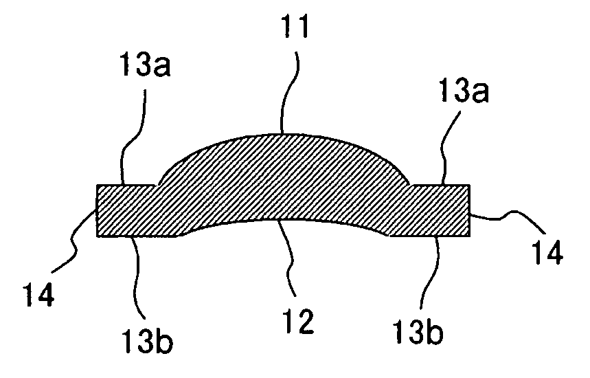
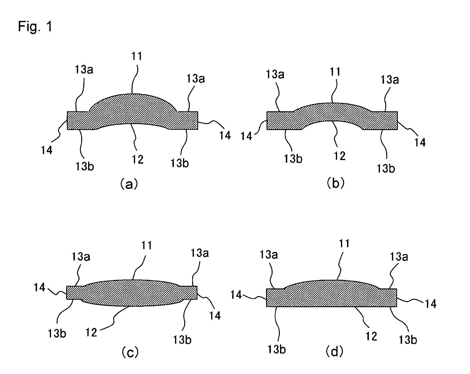
Image

Examples
examples
[0113] The present invention will be explained further in detail with reference to Examples hereinafter, while the present invention shall never be limited by these Examples.
[0114] Phosphates, fluorides, etc., corresponding to glass components, were used as raw materials for a glass, and the raw materials were weighed so as to obtain a glass having a composition shown in Table 1-1 or Table 1-2 and fully mixed, and then the mixture was charged into a platinum crucible and melted with stirring under heat for 1 to 3 hours at a temperature range of 850 to 950° C. in atmosphere in an electric furnace. A homogenized and refined glass melt was cast into a 40×70×15 mm die made of carbon. A cast glass was allowed to cool to a transition temperature and immediately thereafter the cooled glass was transferred into an annealing furnace, annealed around the transition temperature for 1 hour and gradually cooled to room temperature in the annealing furnace. In the above manner, optical glasses s...
PUM
| Property | Measurement | Unit |
|---|---|---|
| Glass transition temperature | aaaaa | aaaaa |
Abstract
Description
Claims
Application Information
 - R&D
- Intellectual Property
- Life Sciences
- Materials
- Tech Scout
- Unparalleled Data Quality
- Higher Quality Content
- 60% Fewer Hallucinations
Browse by: Latest US Patents, China's latest patents, Technical Efficacy Thesaurus, Application Domain, Technology Topic, Popular Technical Reports.
© 2025 PatSnap. All rights reserved.Legal|Privacy policy|Modern Slavery Act Transparency Statement|Sitemap|About US| Contact US: help@patsnap.com