Dual Leaky Bucket Flow Control Method and System

a flow control and leaky bucket technology, applied in the field of communication traffic flow control methods and systems, can solve the problems of increasing the accuracy of the rate being measured by the lower bucket, increasing the error rate, and reducing the accuracy of the leaky buck

Active Publication Date: 2008-04-10
INTEL CORP
View PDF8 Cites 46 Cited by
  • Summary
  • Abstract
  • Description
  • Claims
  • Application Information

AI Technical Summary

Benefits of technology

[0009]A method for scheduling a network resource comprises adding tokens to first and second accumulators at first and second fill rates, respectively. A number of tokens corresponding to a size of a packet is subtracted from the first accumulator and a highest priority is assigned to a queue with which the packet is associated, if a number of tokens in the first accumulator is greater than zero. The number of tokens is subtracted from the second accumulator, and a default priority assigned to the queue, if the number of tokens in the first accumulator is less than zero and a number of tokens in the second accumulator is greater than zero. The network resource is assigned for transmission of the packet from the queue using a schedule that is based on the priority assigned to the queue. The packet is transmitted using the assigned network resource.

Problems solved by technology

In the independent leaky bucket approach, if the maximum rate for a queue is set to the line rate and the minimum rate is set to something very low, and large packets are scheduled to this queue over an extended period, the lower leaky bucket will become extremely negative as packets are drained.
This translates into cumulative error.
The rate being measured by the lower bucket will be inaccurate, and more inaccurate as these events occur.
Such a load could cause the lower shaper to become extremely negative.
Because this rate measuring error is cumulative, the lower shaper would become more and more inaccurate as these types of clipping events occur.

Method used


Image

  • Dual Leaky Bucket Flow Control Method and System
  • Dual Leaky Bucket Flow Control Method and System
  • Dual Leaky Bucket Flow Control Method and System

Examples


example

[0056]FIGS. 4A and 4B show the lower and upper accumulator states for a case in which four 9K packets are scheduled back-to-back by way of the same queue. The update period for the accumulators is 7000 clock cycles. The maximum transmission rate is roughly 4000 bytes per accumulator update cycle, so it takes approximately 2¼ update periods, or 18,000 cycles to process one 9K packet.

[0057]In this example, the upper shaper's delta / limits are set to 4000, or the maximum rate allowed.

[0058]The minimum rate is set to 2000, which equates to about half of the maximum rate. Since only the first packet is sent at high priority, the next high priority packet occurs at (2×2¼) update periods which equates to every other packet, or half of the maximum rate which is exactly what is expected.

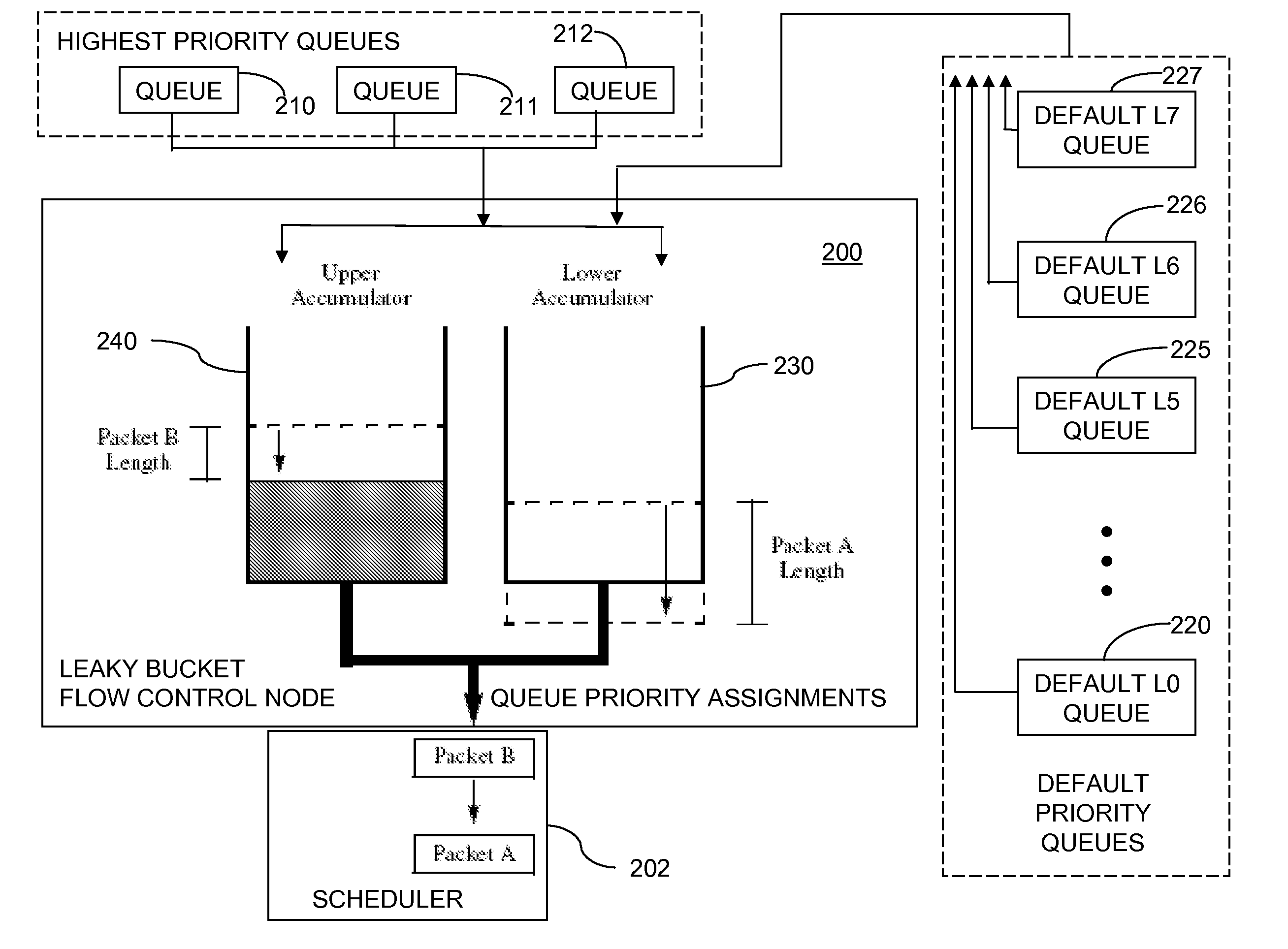
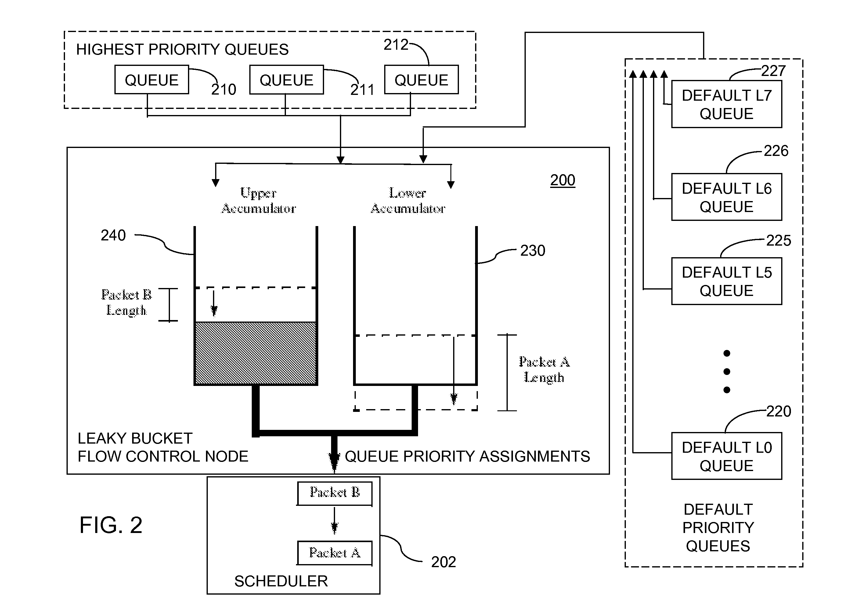
[0059]The linked approach to the token accounting described above serves to unify the two physically separate accumulators 230, 240 into one logical leaky bucket. The lower shaper 230 ensures a minimum packet ...


PUM


Abstract

A method for scheduling a network resource comprises adding tokens to first and second accumulators at first and second fill rates, respectively. A number of tokens corresponding to a size of a packet is subtracted from the first accumulator and a highest priority is assigned to a queue with which the packet is associated, if a number of tokens in the first accumulator is greater than zero. The number of tokens is subtracted from the second accumulator, and a default priority assigned to the queue, if the number of tokens in the first accumulator is less than zero and a number of tokens in the second accumulator is greater than zero. The network resource is assigned for transmission of the packet from the queue using a schedule that is based on the priority assigned to the queue. The packet is transmitted using the assigned network resource.

Description

FIELD OF THE INVENTION[0001]The present invention relates to communications traffic flow control methods and systems.BACKGROUND[0002]Open loop flow control mechanisms are used in asynchronous networks, such as Ethernet (802.3) local area networks (LANs) and asynchronous transfer mode (ATM) networks. These mechanisms may include admission control, policing, and traffic shaping. For admission control, when an application requests a network connection, the application identifies its quality of service (QoS) requirements, and the network decides whether to accept or reject the request. In policing, the network monitors the traffic. Packets from any application that introduces more traffic than identified during network connection setup may be discarded, delayed, or shaped.[0003]Traffic shaping changes the traffic flow to smooth bursty traffic. One type of leaky bucket traffic shaper stores incoming packets in a buffer and releases the packets at a desired rate. The buffer size determine...

Claims


Application Information

Patent Timeline
Patent Type & Authority Applications(United States)
IPC IPC(8): H04L12/50
CPCH04L47/10H04L47/215H04L47/21
Inventor CHIN, KENCHUNG, EDGARRAO, GOPAL MADHAVA
Owner INTEL CORP
Why Eureka
Try Eureka