
Intra-Bundle Power Line Carrier Current System

a power line carrier and current system technology, applied in the direction of digital transmission, power distribution line transmission, single ac network with different frequencies, etc., can solve the problems of difficult to sustain a signal with one conductor out of service, the need for many repeater stations poses an economic burden on the power line carrier communication option, and the loss of radio frequency signal strength. , to achieve the effect of less vulnerability to external interference and greater transmission distan

Inactive Publication Date: 2008-04-10
BARTHOLD LIONEL O +1
View PDF13 Cites 214 Cited by
  • Summary
  • Abstract
  • Description
  • Claims
  • Application Information

AI Technical Summary

Benefits of technology

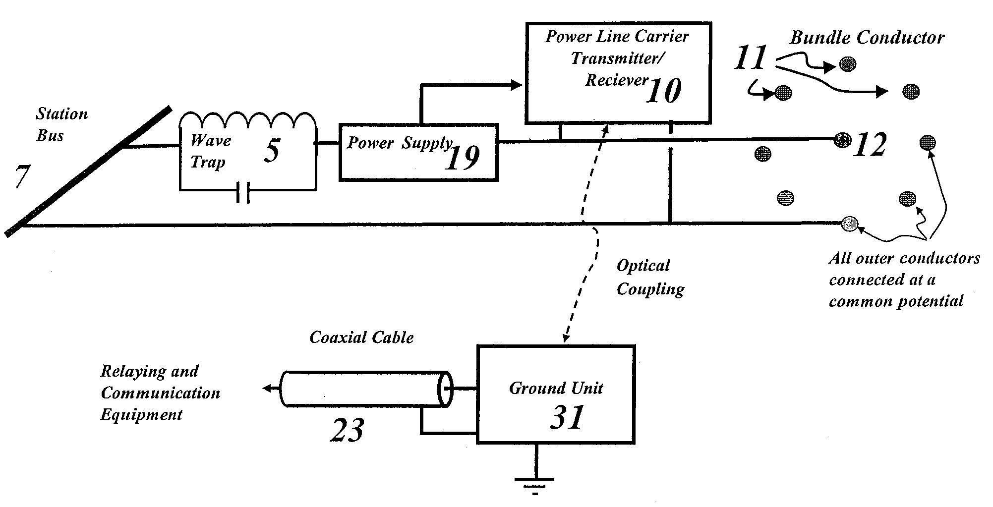
[0018]The invention is directed to applying radio frequency signals between several conductors within a “phase” of an ac transmission line or a “pole” of a dc transmission line rather than between several phases or poles of such transmission line in a manner that gains the benefits characteristic of co-axial cable. Those benefits include greater transmission distance, less vulnerability to external interference, as well as the ability to carry several redundant channels on the same transmission line.
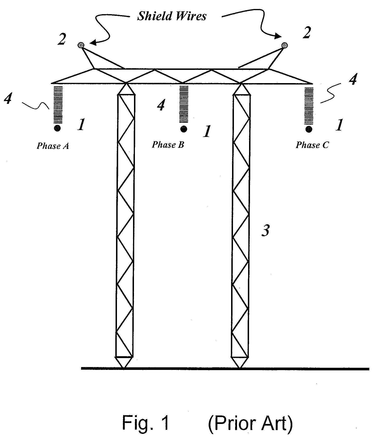
[0021]The physical position occupied by each phase of a three phase ac power line is normally interchanged (transposed) at least once over the length of the line in order that phases a, b, and c, all occupy the same physical position on the tower for the same distance. This eliminates electrical unbalance resulting from the lack of electrical symmetry in the configuration of the phases. Points of transposition cause a drop in strength of inter-phase power line carrier signals. However, points of transposition cause no signal loss for signals contained within the bundle itself, as with the inventive intra-bundle power line carrier system.Noise Vulnerability
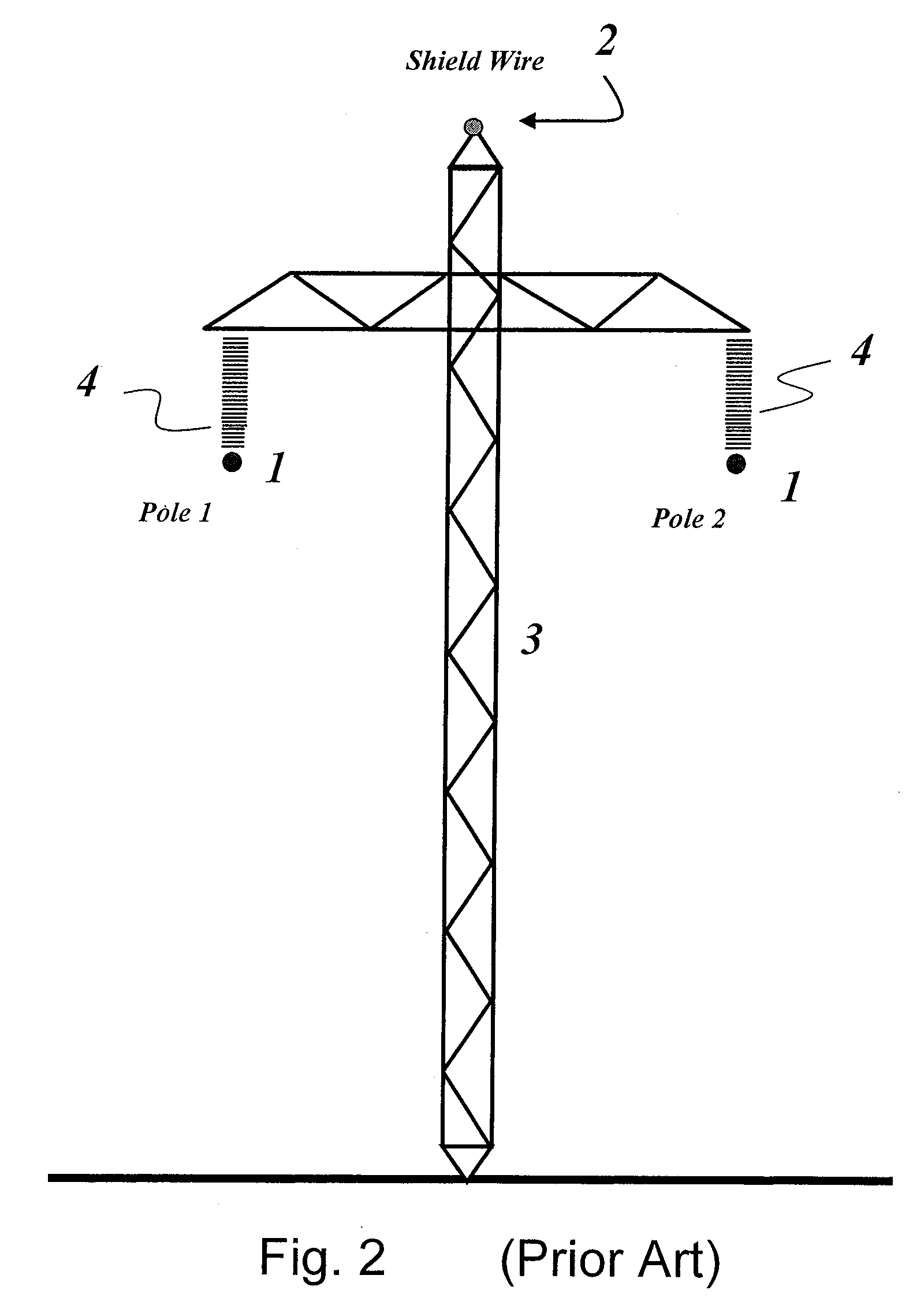
[0022]Noise on a carrier signal is due largely to atmospheric effects and to corona discharges on the conductor surfaces, the latter being generated on both active conductors and on shield wires. The inventive intra-bundle system will tend to shield the center conductor from externally generated noise in the same sense as a co-axial cable would. That benefit applies equally well to noise generated by corona generated on external conductors of the host conductor bundle itself. A corona discharge on one such conductor will be closely coupled electrostatically and electromagnetically to other conductors within the same bundle. Thus the difference in voltage between any two conductors will be very small.

Problems solved by technology

With widely separated conductors of that sort, some of the resulting radio-frequency field is coupled to the earth which, because of its high resistance, causes a gradual loss in radio-frequency signal strength, thus requiring periodic “repeater” stations, i.e. stations which take a weak signal, amplify it, and re-apply it to the line.
For transmission lines of very high voltage and considerable length, the need for many repeater stations poses an economic burden to the power line carrier communication option.
Furthermore, the fact that inter-phase or inter-pole transmission requires continuity in two or more conductors makes it difficult to sustain a signal with one conductor out of service.
Finally, a transmission medium with widely spaced conductors is quite vulnerable to electrical noise, e.g. the “static” caused by corona or electrical impulses resulting from lightning strokes in the vicinity of the line.
The existence of radio frequency fields within the earth causes high losses.
Because of their wide separation, a significant portion of the electric and magnetic field is within the earth, leading to relatively high energy loss and high attenuation.
Widely-spaced conductors also cause the applied radio frequency voltage to be propagated to points far from the line, thus requiring that the applied signal be relatively weak to meet propagation standards.
Conversely, externally-generated noise, e.g. static generated by corona on either or both conductors or, on a larger scale, electrical impulses caused by lighting discharges in the vicinity of the line, will superimpose itself on whatever signal is received between widely spaced conductors, thus interfering with the received signal-potentially causing errors in data received.

Method used


Image

  • Intra-Bundle Power Line Carrier Current System
  • Intra-Bundle Power Line Carrier Current System
  • Intra-Bundle Power Line Carrier Current System

Examples


Embodiment Construction

[0051]FIGS. 9 through 13 illustrate the invention as it applies to bundles of from three to nine conductors per phase in the case where the outer conductors are generally circularly arrayed. In FIG. 9, a three-conductor bundle is accomplished with a central conductor 12, located midway between outer conductors 11 that are arranged in a generally circular configuration as shown by the dotted line. This configuration allows central conductor 12 to comprise one path for radio frequency carrier current energy, and outer conductors 11, connected in parallel, to constitute the return path. FIG. 10 through 13 show corresponding applications extending from four to nine-conductor bundles; the latter coming closest to the properties of a coaxial cable. In each case, the center conductor is insulated from the outer conductors for approximately 100 volts—a voltage sufficient for the radio frequency signal itself. All conductors, including the center conductor 12, will share in carrying power-fr...


PUM


Abstract

A system including associated equipment for transmitting radio-frequency power line carrier signals on high voltage ac or dc transmission lines within a multi-conductor bundle, one path for which is provided by one or more conductors located at the center of the bundle, and the other by the remaining conductors connected in electrical parallel and arrayed in a generally circular pattern around the center. Insulated conductor spacers hold the conductors in their symmetrical configuration and insulate the center conductor, allowing it to serve as a radio frequency path similar to that in a conventional coaxial cable. The system provides low attention, low vulnerability to external noise and low radiation of the carrier signal while providing redundant channels—three for ac transmission lines and two for bipolar dc transmission lines.

Description

CROSS REFERENCE TO RELATED APPLICATIONS [0001]This application claims priority of Provisional patent application Ser. No. 60 / 828,803 filed Oct. 10, 2006, the disclosure of which is incorporated herein by reference.FIELD OF THE INVENTION [0002]The invention pertains to superimposing radio frequency signals onto the conductors of electric cables or conductors, the primary use of which is to carry electric power; commonly referred to as “Power Line Carrier Current.”BACKGROUND OF THE INVENTION [0003]Since the early 1900's, it has been common to superimpose a radio frequency signal on electric power transmission lines and use that signal for control and communication functions at both ends of the line. Prominent among those functions is the sending of information on current and voltage levels, thus allowing protective relays to judge whether or not to cause circuit breakers to open and take the line out of service.[0004]The radio frequency signal is generally applied between two phases o...

Claims


Application Information

Patent Timeline
IPC IPC(8): H04B3/00
CPCH04B3/56H04B2203/5483H04B3/58Y10S307/01
Inventor BARTHOLD, LIONEL O.WOODFORD, DENNIS A.
Owner BARTHOLD LIONEL O
Learn More