Eureka AIR delivers breakthrough ideas for toughest innovation challenges, trusted by R&D personnel around the world.

Substrate polishing apparatus and method

Active Publication Date: 2008-04-10
EBARA CORP
View PDF8 Cites 32 Cited by
  • Summary
  • Abstract
  • Description
  • Claims
  • Application Information

AI Technical Summary

Benefits of technology

[0015]It is therefore an object of the present invention to provide a polishing apparatus and method, and a substrate receiving method which will solve the above problems (1) through (7) and are capable of polishing large-size glass substrates to higher planarization and cleaning and drying the polished large-size glass substrates.

Problems solved by technology

However, the process of using silver paste has been problematic in that such process is highly costly and experiences difficulty in producing fine interconnections.
(1) A large-size glass substrate needs to be reliably held against and attracted to the holding surface (flat surface) of the substrate holder. However, the large-size glass substrate is thin and highly liable to be deformed or bent. Furthermore, a glass substrate which is plated with copper or the like before it is polished tends to be warped and is highly likely to break. Such a tendency has to be held to a minimum.
(2) If particles and foreign matter is trapped between the holding surface of the substrate holder and the surface of the glass substrate, then the glass substrate tends to be broken while it is being polished. Therefore, it is necessary to prevent particles and foreign matter from being trapped between the holding surface of the substrate holder and the surface of the glass substrate.
(3) When a large-size glass substrate is polished, the polishing pad on the upper surface of the turntable and the glass substrate have large contact areas, respectively, and produce a large amount of frictional heat. A large amount of heat is also produced by the chemical reaction of the slurry (polishing liquid) or the like. These amounts of heat have to be lowered.
(4) A large amount of slurry (polishing liquid) is required to polish a large-size glass substrate. For reducing the cost of the process of polishing the glass substrate, it is necessary to reduce the amount of the slurry (polishing liquid) which is consumed in the polishing process.
(5) The large-size glass substrate is attracted by the substrate holder through an attracting surface (holding surface) of the substrate holder which has a large attracting area, and is held in close contact with the attracting surface under surface tension. After the glass substrate is polished, therefore, the glass substrate is highly difficult to release (remove) in its entirety from the attracting surface in one direction under uniform forces, and may possibly be damaged when it is removed from the substrate holder. It is necessary to release (remove) the glass substrate from the attracting surface of the substrate holder without causing damage to the glass substrate.
(6) The CMP apparatus requires a large-size cleaning unit for cleaning the large-size glass substrate which has been polished. Generally, the CMP apparatus has a glass substrate transfer unit such as a robot for transferring the glass substrate to the cleaning unit after the glass substrate is polished. However, the glass substrate transfer unit for transferring the large-size glass substrate makes it difficult to make the CMP apparatus more compact and less costly.
(7) The polishing pad attached to the upper surface of the turntable is a consumable product that needs to be replaced after it has reached the end of its service life. However, the polishing pad on the large-size turntable cannot easily be replaced in a short period of time. Therefore, it is necessary to facilitate replacement of the polishing pad for shortening machine downtime.

Method used


Image

  • Substrate polishing apparatus and method
  • Substrate polishing apparatus and method
  • Substrate polishing apparatus and method

Examples


Embodiment Construction

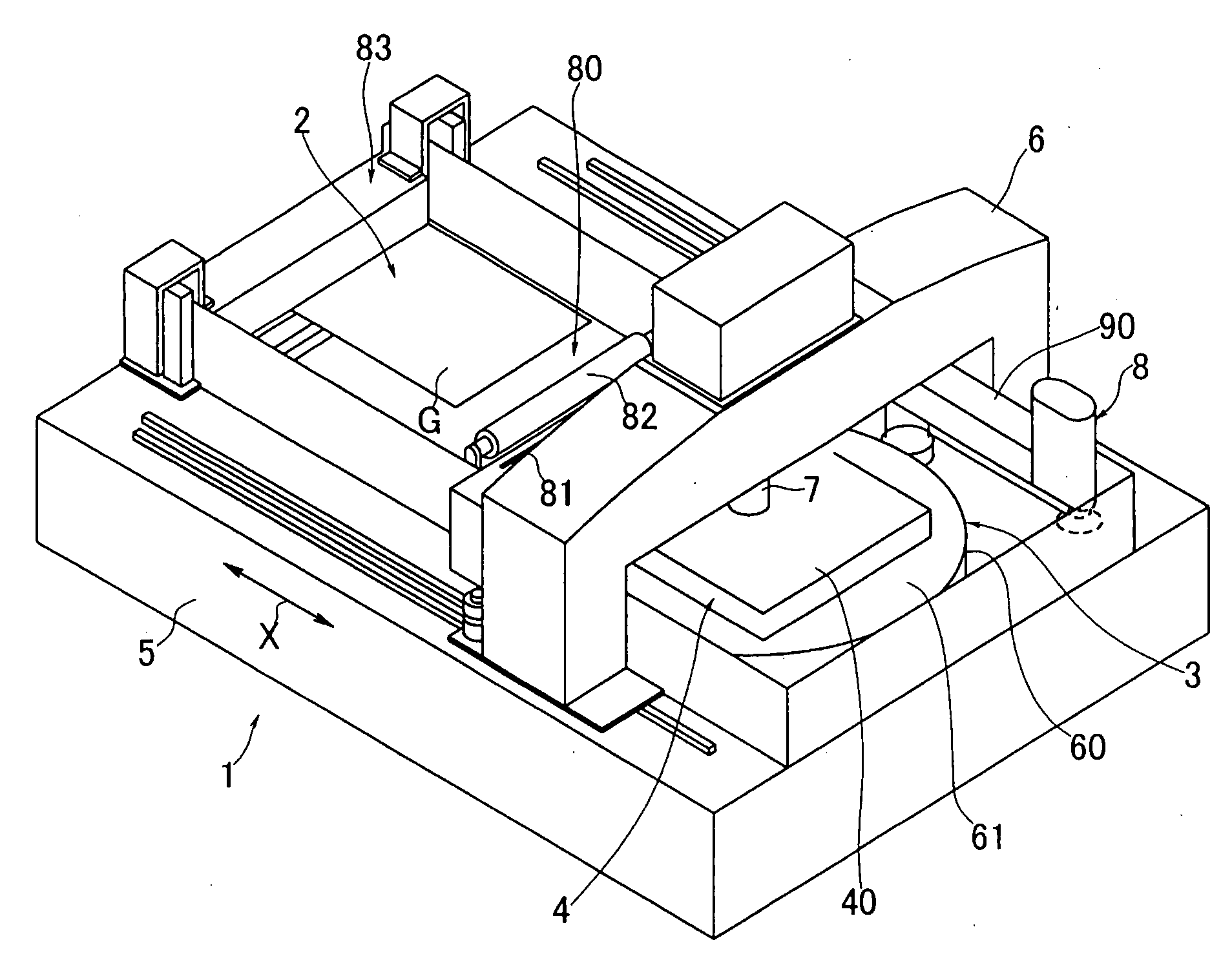
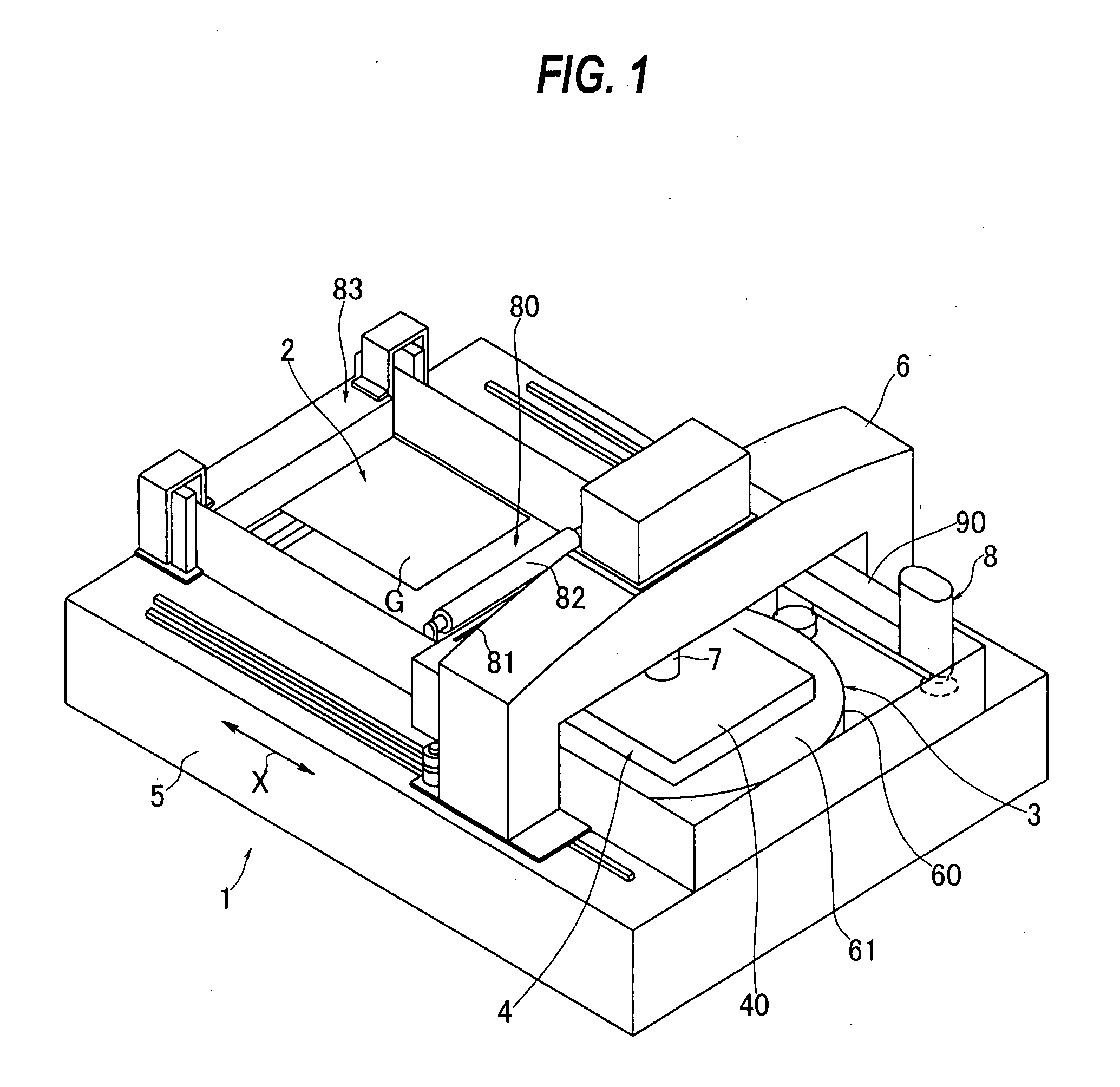
[0095]A substrate polishing apparatus according to the present invention will be described in detail below with reference to the drawings. FIG. 1 shows in perspective the substrate polishing apparatus according to the present invention. As shown in FIG. 1, the substrate polishing apparatus, generally denoted by 1, comprises a pusher mechanism 2, a polishing mechanism 3, and a substrate holding mechanism 4. The pusher mechanism 2 transfers a substrate to and from a transfer robot (not shown) and also transfers a substrate to and from the substrate holding mechanism 4. The pusher mechanism 2 constitutes a substrate transfer mechanism. The polishing mechanism 3 polishes a substrate held by the substrate holding mechanism 4. The substrate holding mechanism 4 holds a substrate to be polished and polishes the substrate in cooperation with the polishing mechanism 3. The substrate to be polished comprises a glass substrate, and is simply referred to as a substrate G. The substrate polishing...


PUM

PropertyMeasurementUnit
Pressureaaaaaaaaaa
Widthaaaaaaaaaa
Areaaaaaaaaaaa

Abstract

A substrate polishing apparatus includes a substrate holding mechanism having a head for holding a substrate to be polished, and a polishing mechanism including a polishing table with a polishing pad mounted thereon. The substrate held by the head is pressed against the polishing pad on the polishing table to polish the substrate by relative movement of the substrate and the polishing pad. The substrate polishing apparatus also includes a substrate transfer mechanism for delivering the substrate to be polished to the head and receiving the polished substrate. The substrate transfer mechanism includes a substrate to-be-polished receiver for receiving the substrate to be polished, and a polished substrate receiver for receiving the substrate which has been polished.

Description

BACKGROUND OF THE INVENTION[0001]1. Field of the Invention[0002]The present invention relates to a substrate polishing apparatus and method, and more particularly to a substrate polishing apparatus and method suitable for polishing an insulating material layer or an conductive material layer on a large-size glass substrate. Further, the present invention relates to a substrate receiving method.[0003]2. Description of the Related Art[0004]Transparent glass substrates for use in solar cells and flat displays have circuits formed thereon using silver paste by printing. However, the process of using silver paste has been problematic in that such process is highly costly and experiences difficulty in producing fine interconnections.[0005]As image display apparatuses typified by liquid crystal displays have become larger in size, glass substrates used therein also have become larger in size. For producing fine interconnections for those larger image display apparatuses and reducing the co...

Claims


Application Information

Patent Timeline
IPC IPC(8): B24B55/02B24B7/24B24B37/00B24B37/015B24B37/04B24B37/12B24B37/30B24B41/06B24B53/017B24B53/02
CPCB24B37/04Y10S451/914B24B55/02H01L21/304
Inventor KATSUOKA, SEIJISEKIMOTO, MASAHIKOKUNISAWA, JUNJIMIYAZAKI, MITSURUWATANABE, TERUYUKIKOBAYASHI, KENICHIKUMEKAWA, MASAYUKIYOKOYAMA, TOSHIO
Owner EBARA CORP
Why Eureka
Eureka Blog
Learn More