Wave Activated Power Generation Device And Wave Activated Power Generation Plant

a technology of power generation device and power generation plant, which is applied in the direction of electric generator control, machines/engines, mechanical equipment, etc., can solve the problems of increasing construction costs, increasing construction costs, and increasing construction costs, so as to reduce device manufacturing cost and installation cost, and improve maintenance performance and safety performance. , the effect of excellent performan

Inactive Publication Date: 2008-04-17
TOYO TECHNOS CO LTD
View PDF11 Cites 37 Cited by
  • Summary
  • Abstract
  • Description
  • Claims
  • Application Information

AI Technical Summary

Benefits of technology

[0007]The present invention was conceived in consideration of the circumstances mentioned above and an object of the present invention is to provide a wave activated power generation device and a wave activated power generation plant utilizing the same capable of reducing the device manufacturing cost and installation cost, and having no necessity of fixing to a sea bed, being excellent in maintenance performance and safety performance, and being applied no influence to a neighboring appearance
[0021]The wave activated power generation device may further include a watertight control chamber provided at the upper portion of the floating body, and an automatic valve provided in the control chamber, wherein the automatic valve automatically performs an opening operation in response to a detection of sea wind force larger than a undetermined value, so that the overall wave activated power generation device is evacuated into the water by discharging gas inside the buoyancy control chamber so as to decrease the buoyancy of the wave activated power generation device.
[0036]According to the wave activated power generation device and wave activated power generation plant of the present invention having the above described features, because the floating body that forms a device body is not fixed to the sea floor but it is anchorable, its management is easy and it is much less likely to be damaged by the size of wave. In addition, in the depth of the sea where water is almost stationary without being affected by surface waves, resistance of water becomes extremely large when the floating body is moved up and down by the difference between buoyancy and weight, whereas near the surface of the sea, force applied to the floating body due to wares becomes minimum, so that power generation may efficiently be performed utilizing wave energy.
[0037]In addition because the natural period T of vertical motion of the floating body is determined in the range of 0.8 to 1.6 times an annual average wave period at an anchored area, a phase difference between the ware motion and the vertical motion of the floating body is approximately 90 degrees. This can make the difference of the vertical position between the wave and the floating body to be equal to or more than the height of the wave. Hence, the conversion efficiency of wave energy may be improved
[0038]Moreover, because a generator is driven by means of an air turbine that is always rotated in one direction independently from the direction of reciprocating air flow, it is advantageous if that the conversion efficiency of wave energy may be improved.
[0039]Furthermore, because the floating body is divided into three sections, that is, a upper portion, a intermediate portion, and a lower portion, and the intermediate portion is constructed by connecting unit members each having a predetermined axial length. The overall length of the floating body may be selected by changing the number in which the unit length members of the intermediate portion are provided in accordance with the depth of the sea, annual average wave height, annual average wave period, or the like. Thus, it is applicable to wide range of installation conditions without any change in the basic design. As a result, it is advantageous in standardization and mass production.

Problems solved by technology

Nevertheless, due to the reasons, such as 1) high costs, 2) extensive safety measures, and 3) blot on the landscape, wave power generation has not spread in earnest.
However, the existing devices described in Patent Document 1 and Patent Document 3 require excessively complex mechanism and controlling operation nd, therefore, have a drawback in that the costs of construction and maintenance may not be reduced so much.
The existing device described in Patent Document 2 also has a drawback in that, because the device is settled on the sea floor, the costs of safety measures for construction and maintenance may not be reduced so much, and, in addition, because disassembly for maintenance is troublesome, it requires a lot of man hours and an extended construction period.
Furthermore, it also has a drawback in that trying to increase the efficiency using a wells turbine increases costs accordingly.
The existing device described in Patent Document 4 has a drawback in that, because a platform portion located on the surface of the sea is spherical in shapes it is largely effected by vertical motion of waves, thus impeding collection of wave energy.

Method used


Image

  • Wave Activated Power Generation Device And Wave Activated Power Generation Plant
  • Wave Activated Power Generation Device And Wave Activated Power Generation Plant
  • Wave Activated Power Generation Device And Wave Activated Power Generation Plant

Examples


Embodiment Construction

[0059]Hereinafter, an embodiment according to the present invention will be described with reference to the accompanying drawings.

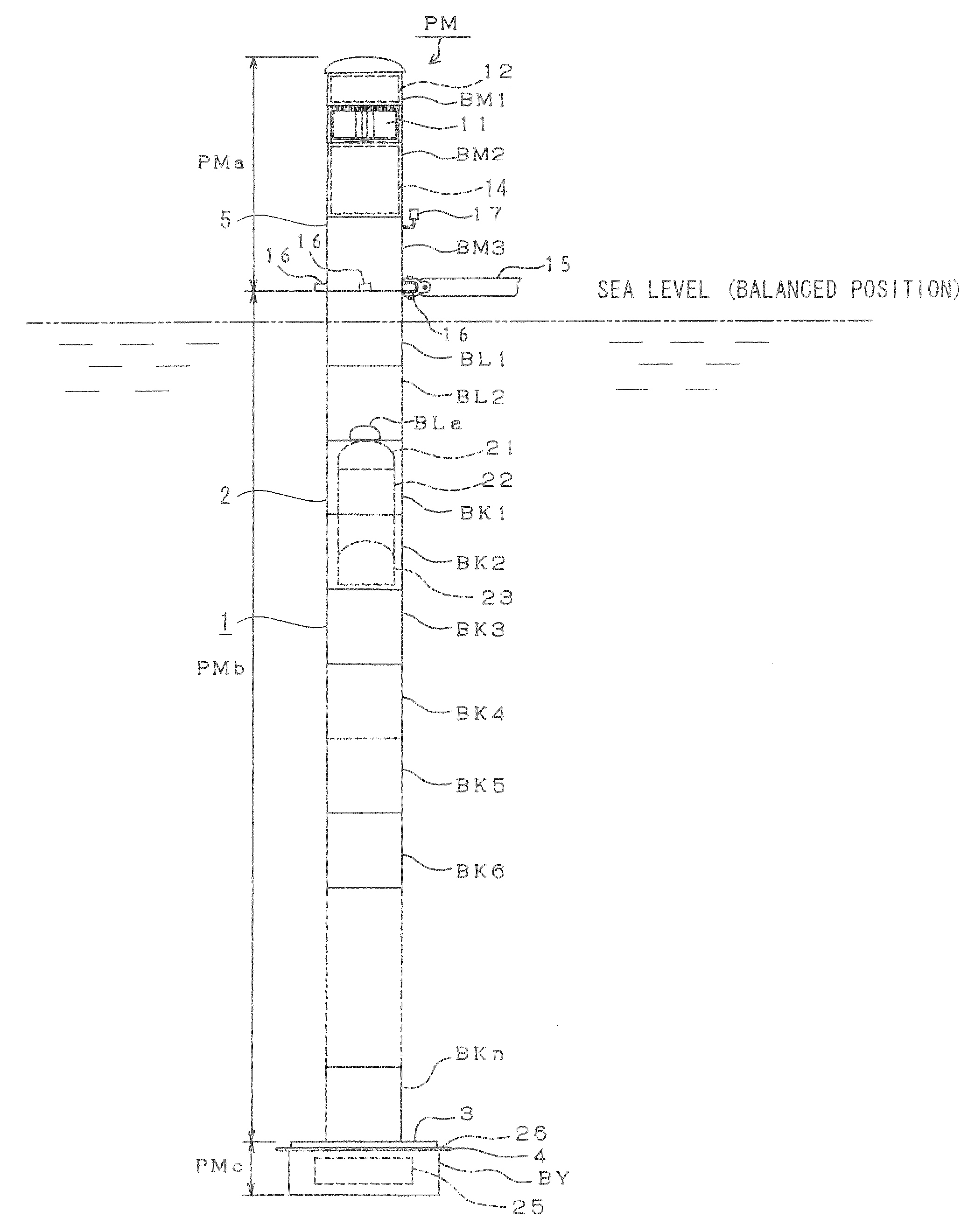
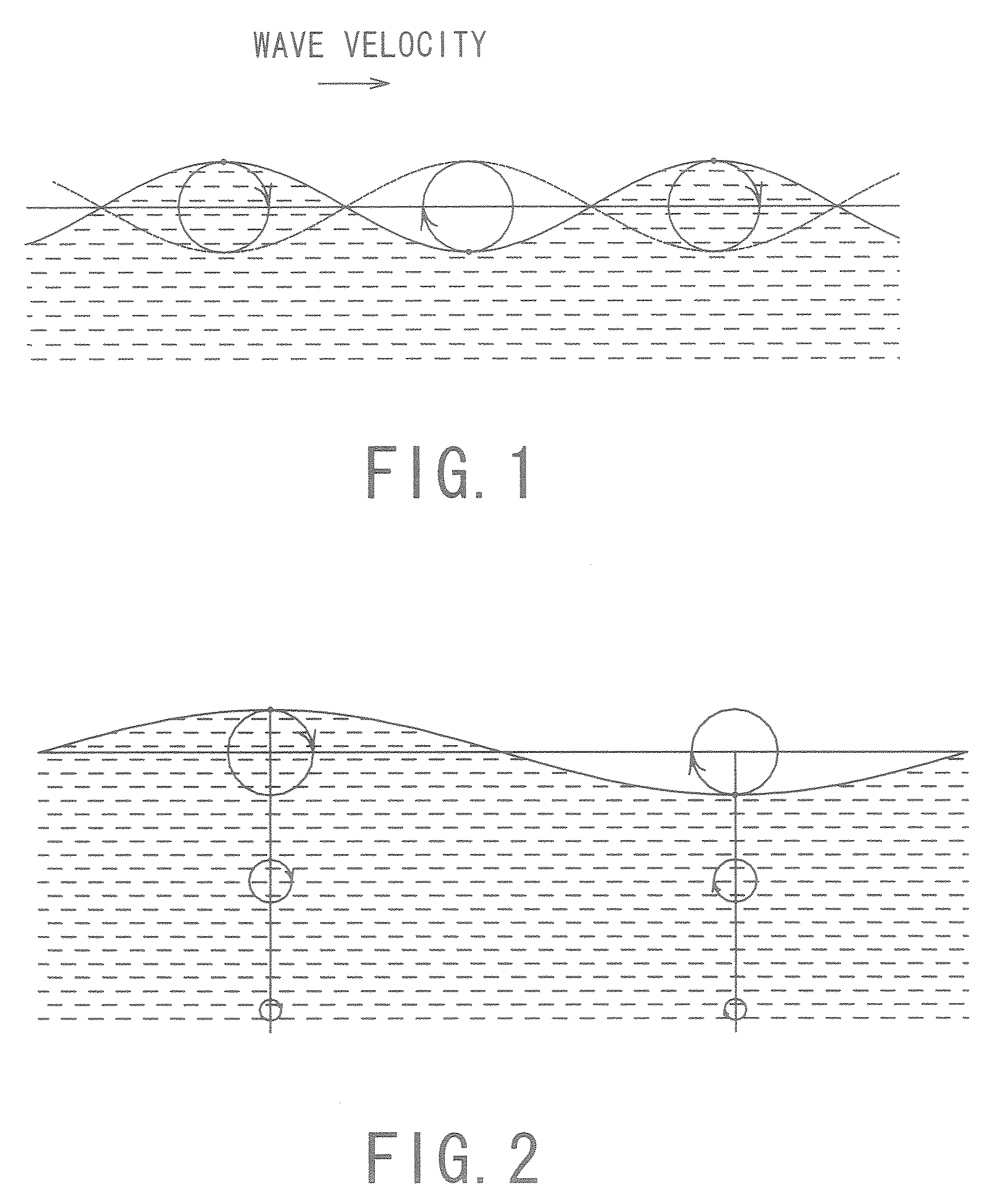
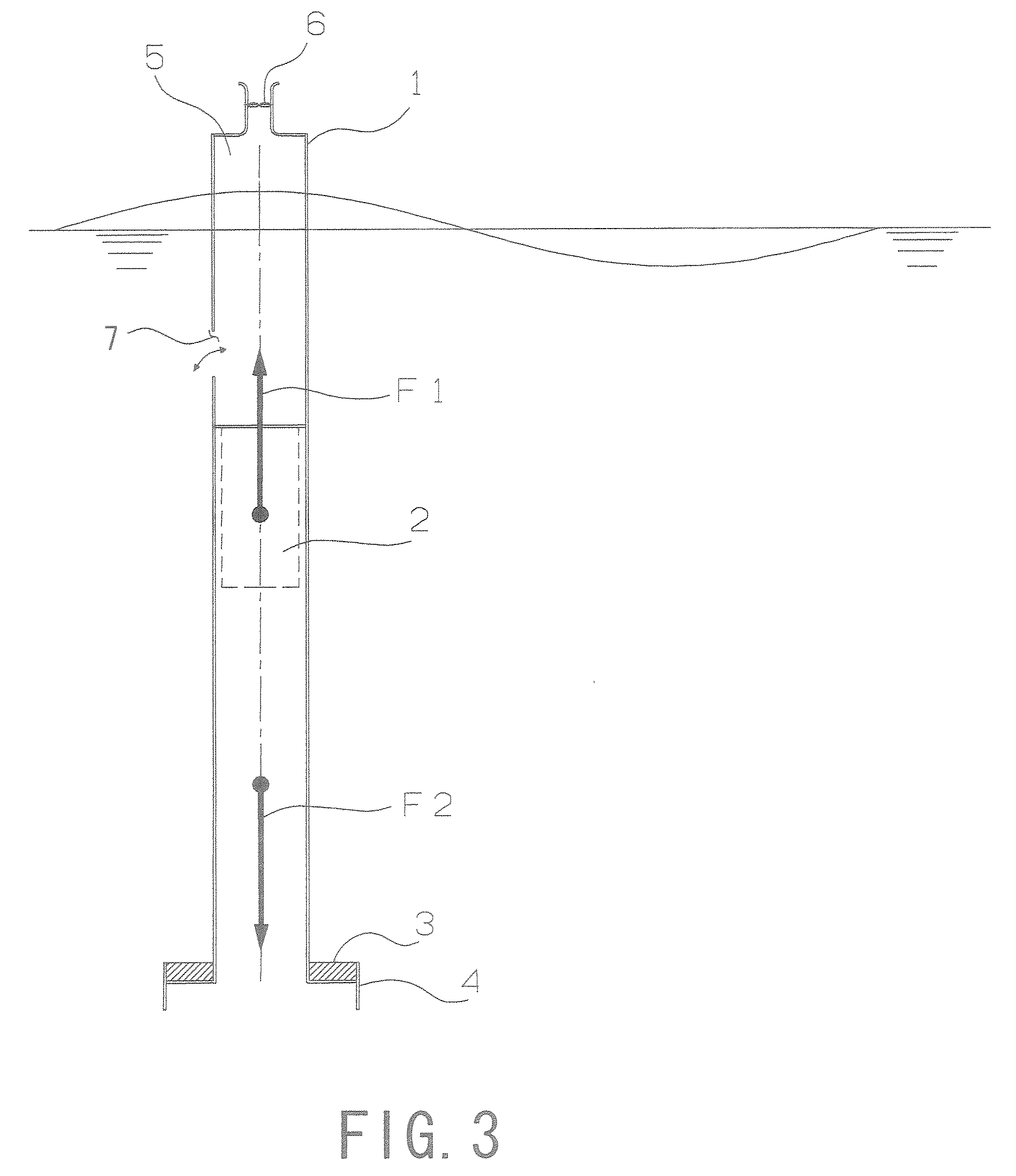
[0060]The present invention provides a device that performs wave power generation by converting wave (wave power) energy, that comes from the vertical motion of waves into electric energy to collect the electric energy. First, the principles of the present invention will be described with reference to FIG. 1. It is to be noted that the following description is made on the assumption that a floating body (which will be described later) are installed in the sea However, even in water areas such as lakes, a floating body according to the present invention may be located. In addition, in the following description, it should be understood that the description related to directions, such as upper, lower, right, and left, is referred to under the condition that the wave activated power generation device is installed so as to float in water unless otherwise expli...


PUM

PropertyMeasurementUnit
weightaaaaaaaaaa
areaaaaaaaaaaa
massaaaaaaaaaa

Abstract

A wave activated power generation device includes a cylindrical floating body anchored on water and extending vertically to a water surface. a ba last provided at a lower end portion of the floating body and a power generating equipment provided at an upper end portion of the floating body The floating body includes a buoyancy control chamber allowing the floating body to vertically float in the water and adjusting a position of the floating body relative to the water surface to a predetermined height in accordance with a relation between buoyancy of the floating body and weight of the ballast, ad an air chamber formed between the buoyancy control chamber and the power generating equipment. The power generating equipment includes an air turbine provided above the air chamber and driven by air flow generated between a inside and outside of the air chamber by vertical motion of the water surface, ad a generator rotationally driven by the air turbine. Further ore, a wave activated power generation plant includes the coupled plural wave activated power generation devices upon request.

Description

TECHNICAL FIELD [0001]The present invention relates to a wave activated power generation device that is provided with a floating body anchorable on water and a power generating means mounted on the floating body, and that generates electricity using wave energy and also relates to a wave activated power generation plant that includes the wave activated power generation devices.BACKGROUND ART[0002]There is plenty of wave energy in the sea, ad the wave energy is accessible. Because of the accessibility, wave power generation that utilizes wave energy has been studied in va ious manners so far in our country and foreign countries and some experiments have been conducted actually in the sea. Nevertheless, due to the reasons, such as 1) high costs, 2) extensive safety measures, and 3) blot on the landscape, wave power generation has not spread in earnest.[0003]Some existing inventions that utilize wave energy have been proposed, for example, in Japanese Unexamined Patent Application Publ...

Claims


Application Information

Patent Timeline
Patent Type & Authority Applications(United States)
IPC IPC(8): F03D9/00F03B13/24F03D9/02
CPCF03B13/142F03B13/24Y02E10/725Y02E10/38Y02E10/32Y02E10/30Y02E10/72
Inventor NAGATA, YOSHIHIROKONNO, TOSHIO
Owner TOYO TECHNOS CO LTD
Why Eureka
Try Eureka