Target detecting apparatus using electronically agile radar
a target detection and agile technology, applied in the direction of multi-channel direction-finding systems using radio waves, instruments, measurement devices, etc., can solve the problems of difficulty in accurately detecting a target, insufficient resolution, and target placed at a short distance, so as to achieve high distance values and stably detect the target
- Summary
- Abstract
- Description
- Claims
- Application Information
AI Technical Summary
Benefits of technology
Problems solved by technology
Method used
Image
Examples
first embodiment
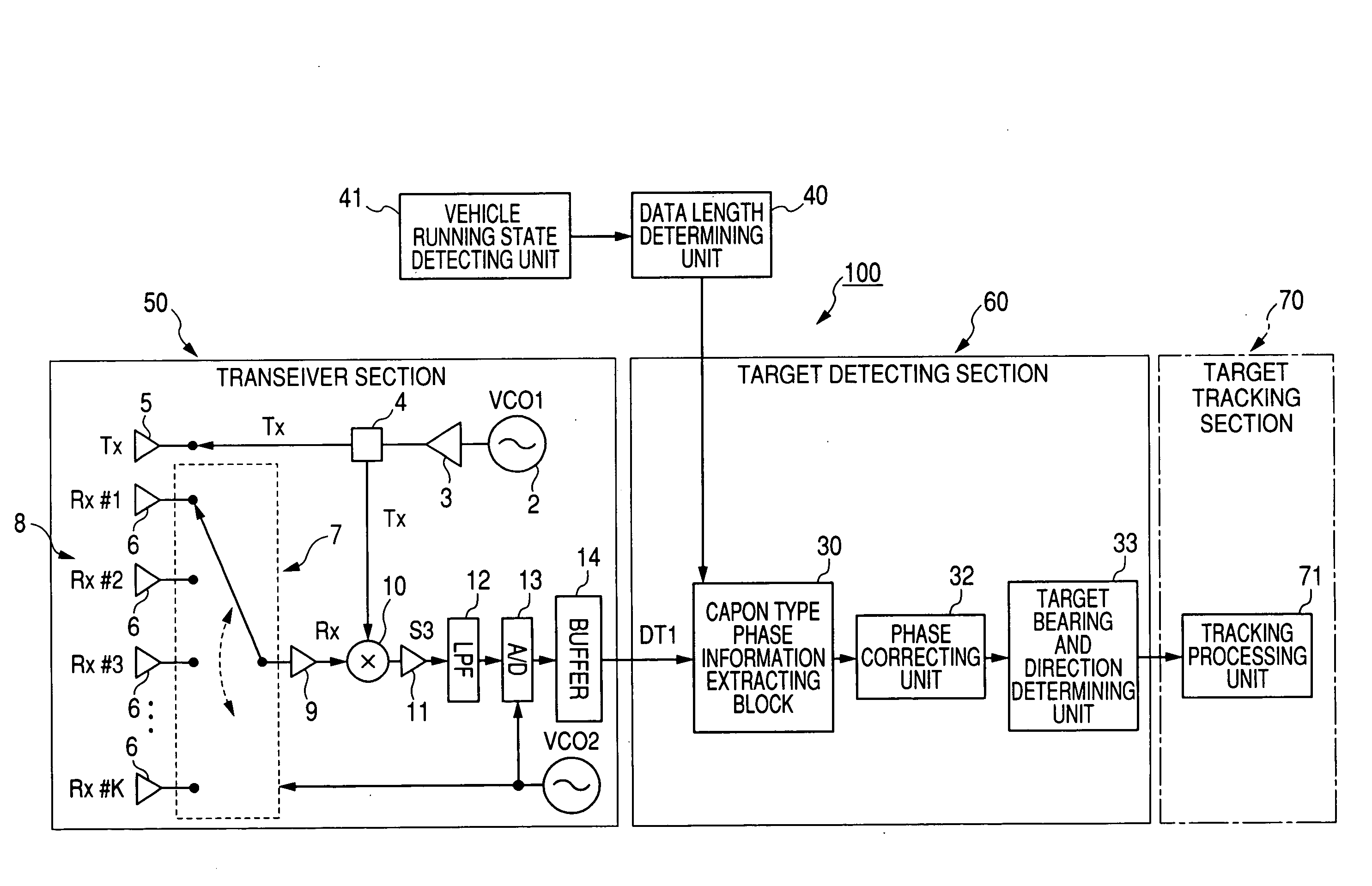
[0042]FIG. 4 is a block diagram of a target detecting apparatus using an electronically agile radar according to the first embodiment, while FIG. 5 is a block diagram of a Capon type phase information extracting unit shown in FIG. 4. FIG. 6 is a view explanatorily showing three search areas determined by dividing a fan-shaped measuring region placed in front of a present vehicle. FIG. 7 is a view schematically showing the processing for extracting short time serial data from sampled digital data.
[0043]An electronically agile radar of a target detecting apparatus 100 shown in FIG. 4 is a type of FM-CW radar for frequency-modulating a continuous wave to obtain a transmission signal Tx having a carrier wave and outputting the signal Tx. The electronically agile radar is also a type of digital beam forming radar for performing the digital beam forming processing for a reception signal Rx received in the radar. A microwave is used as the carrier wave (or radio wave) of the signal Tx. Fur...
first modification
of First Embodiment
[0086]FIG. 11 is a block diagram of a target detecting apparatus using an electronically agile radar according to a first modification of the first embodiment, while FIG. 12 is a block diagram of a variable data length type phase information extracting block shown in FIG. 11.
[0087]As shown in FIG. 11, a target detecting apparatus 110 differs from the apparatus 100 shown in FIG. 4 in that the apparatus 110 has a variable data length type phase information extracting block 42 in place of the block 30. The extracting block 42 extracts, from the reception data DT, phase information expressed by short time serial data of which a data length is changeably adjusted based on a distance of a search area from the present vehicle.
[0088]As shown in FIG. 12, the extracting block 42 has the BPF 18, the extracting unit 19, and a phase information producing unit 43. The producing unit 43 produces phase information from (N−M+1) time series of M short time data of each channel acco...
second modification
of First Embodiment
[0090]FIG. 13 is a block diagram of a target detecting apparatus using an electronically agile radar according to a second modification of the first embodiment, while FIG. 14 is a block diagram of an FFT type phase information extracting block shown in FIG. 13.
[0091]As shown in FIG. 13, a target detecting apparatus 120 differs from the apparatus 100 shown in FIG. 4 in that the apparatus 120 has an FFT type phase information extracting block 44 in place of the block 30. The extracting block 44 extracts, from the reception data DT according to the FFT, phase information expressed by short time serial data of which a data length is changeably adjusted based on a distance of a search area from the present vehicle.
[0092]As shown in FIG. 14, the extracting block 44 has the BPF 18, the extracting unit 19, and an FFT-based phase information producing unit 43. The producing unit 43 produces FFT type phase information from (N−M+1) time series of M short time data of each ch...
PUM
 Abstract
Description
Claims
Application Information
 - R&D
- Intellectual Property
- Life Sciences
- Materials
- Tech Scout
- Unparalleled Data Quality
- Higher Quality Content
- 60% Fewer Hallucinations
Browse by: Latest US Patents, China's latest patents, Technical Efficacy Thesaurus, Application Domain, Technology Topic, Popular Technical Reports.
© 2025 PatSnap. All rights reserved.Legal|Privacy policy|Modern Slavery Act Transparency Statement|Sitemap|About US| Contact US: help@patsnap.com


