Enhanced Passive Coherent Location Techniques to Track and Identify UAVs, UCAVs, MAVs, and Other Objects

a technology of location and coherent location, applied in the field of aircraft tracking, can solve the problems of low frequency band stealth capability, low stealth capability, and inability to detect outgoing signals, etc., and achieve the effect of high confidence in target identification and classification

Inactive Publication Date: 2008-04-17
ERA AS
View PDF99 Cites 126 Cited by
  • Summary
  • Abstract
  • Description
  • Claims
  • Application Information

AI Technical Summary

Benefits of technology

[0062] In another embodiment of the present invention, combined portable or fixed multilateration, ADS-B, PET, and PCL receiver systems share the same mast, power, communications, and infrastructure for ease of deployment.
[0072] In another embodiment of the present invention, electronic intelligence from broadband passive emitter tracking coupled with PCL extracted target characteristics is used to provide high confidence in target identification and classification.

Problems solved by technology

Conventional aircraft stealth technology is not designed for the frequency bands used by PCL.
These stealth capabilities are lost at the lower frequency bands, such as VHF for FM radio.
PCL represents a technological challenge, which must be handled both from a precise antenna and receiver technique point of view, but mainly through the use of sophisticated digital signal processing methods.
According to a recent Newsweek article, US analysts expressed worries that the new early-warning defence system could defeat current US Air Force tactics against enemy air defences.
The Newsweek article went on to state that current defences use radar to track incoming aircraft, but outgoing signals can be found and jammed or destroyed.
The “passive” technology the Chinese are believed to have, detects aircraft by monitoring disruptions in commercial radio and TV signals, and are essentially undetectable, Newsweek reported.
At the time, the military in Taiwan, however, said it was unlikely the development of PCL technology by China has been taken beyond the theoretical stage.

Method used


Image

  • Enhanced Passive Coherent Location Techniques to Track and Identify UAVs, UCAVs, MAVs, and Other Objects
  • Enhanced Passive Coherent Location Techniques to Track and Identify UAVs, UCAVs, MAVs, and Other Objects
  • Enhanced Passive Coherent Location Techniques to Track and Identify UAVs, UCAVs, MAVs, and Other Objects

Examples


first embodiment

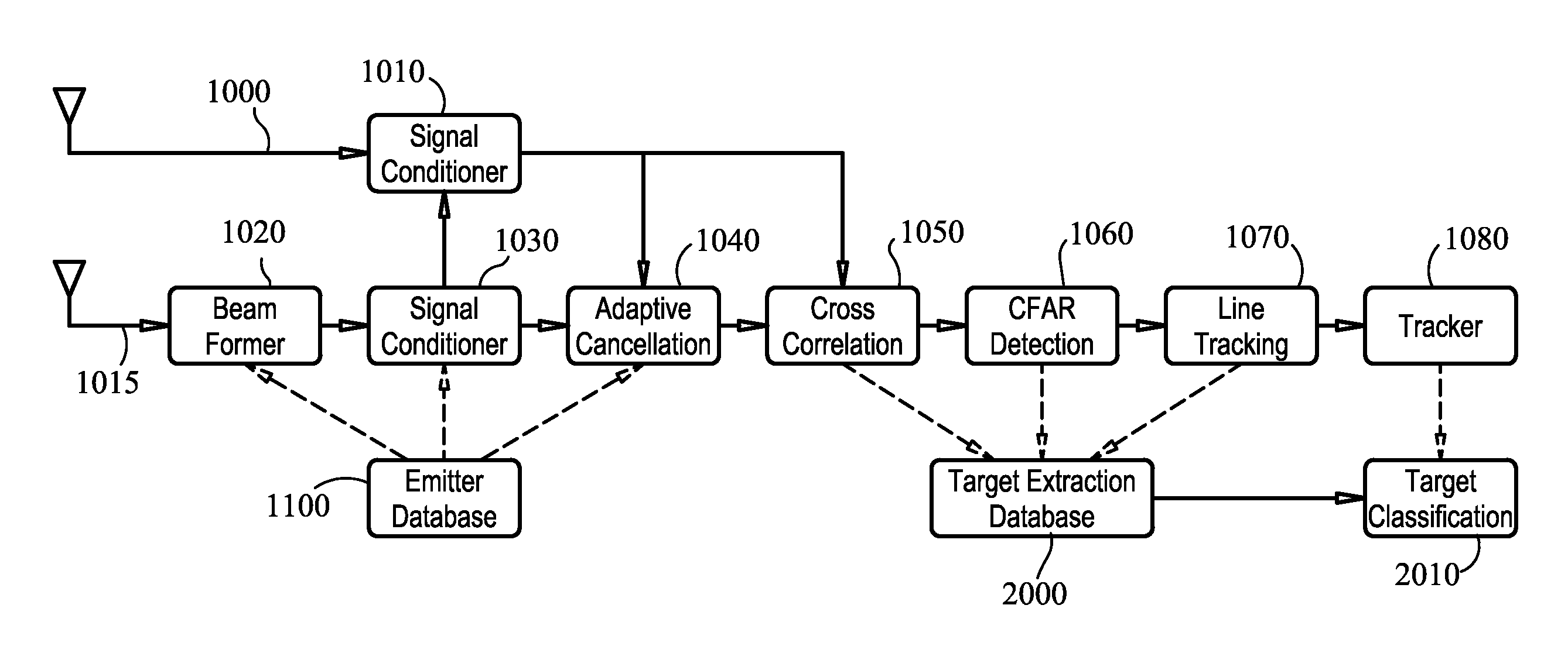
[0079] Referring to FIG. 4, in the present invention, a PCL tracking and identification system is provided as a standalone system. Referring to FIG. 4, reference signal antenna 1000 passes the various reference signals to the signal conditioner 1010. The beam forming antenna 1015 passes the reflected signals through beam former 1010 to the signal conditioner 1030. Like most passive radar systems that use simple antenna arrays with several antenna elements and element-level digitization, this allows the direction of arrival of echoes to be calculated using standard radar beam forming techniques, such as amplitude monopulse using a series of fixed, overlapping beams or more sophisticated adaptive beam forming.

[0080] Signal conditioners 1010 and 1030 perform some transmitter-specific conditioning of the signal before cross-correlation processing. Conditioning includes analogue band-pass filtering of the signal, equalization to improve the quality of the reference signal, and removal of...

second embodiment

[0085] Referring to FIG. 5, in the present invention, PCL tracking and identification is combined with other sources. This embodiment shows the utility of PCL when integrated with other sources of surveillance that include ADS-B, multilateration, broadband emitter tracking, or Passive Emitter Tracking (PET), as well as identification information from all sources including electronic intelligence (ELINT). Aircraft 100 is flying with the range of multilateration / ADS-B receivers and broadband PET receivers, shown as combined receivers for this embodiment 150. Multilateration / ADS-B / PET sensor data is sent to central server 250 using a variety of communications media, including either of fiber, telephone line, wireless, or satellite communications 200.

[0086] The PCL channel consists of a reference antenna and a beam-forming network and is shown separately as 450 but in practice may be co-located with the other sensors 150. The PCL information is processed to provide tracks and target cla...


PUM


Abstract

A system and technique is described which has the capability to track and identify, in real time, various aircraft and objects including Unmanned Aerial Vehicles (UAVs), Unmanned Combat Aerial Vehicles (UCAVs), and Micro Aerial Vehicles (MAVs). The system uses a combination of techniques including conventional automatic dependent surveillance broadcast (ADS-B), transponder multilateration, broadband emitter multilateration, primary and secondary radar, and passive coherent location. A series of enhancement to conventional passive coherent location are described.

Description

CROSS-REFERENCE TO RELATED APPLICATIONS [0001] The present application is a Continuation-In-Part of U.S. patent application Ser. No. 11 / 688,348, filed on Mar. 20, 2007, and incorporated herein by reference; application Ser. No. 11 / 688,348 is a Continuation-In-Part of U.S. patent application Ser. No. 11 / 492,711, filed Jul. 25, 2006, and incorporated herein by reference; application Ser. No. 11 / 688,348 is a Continuation-In-Part of U.S. patent application Ser. No. 11 / 343,079, filed on Jan. 30, 2006, and incorporated herein by reference; application Ser. No. 11 / 688,348 is also a Continuation-In-Part of U.S. patent application Ser. No. 11 / 342,289 filed Jan. 28, 2006 and incorporated herein by reference; application Ser. No. 11 / 688,348 is a Continuation-In-Part of U.S. patent application Ser. No. 11 / 209,030, filed on Aug. 22, 2005, and incorporated herein by reference; application Ser. No. 11 / 688,348 is a Continuation-In-Part of U.S. patent application Ser. No. 11 / 257,416, filed on Oct. 2...

Claims


Application Information

Patent Timeline
Patent Type & Authority Applications(United States)
IPC IPC(8): G01S3/00
CPCG01S5/06G01S13/003G01S13/584G01S13/66H01Q21/29G01S13/86G01S13/878H01Q3/24G01S13/726
Inventor SMITH, ALEXANDER E.
Owner ERA AS
Why Eureka
Try Eureka