Magnetic head for perpendicular magnetic recording and method of manufacturing same

a perpendicular magnetic and recording technology, applied in the field of magnetic head perpendicular magnetic recording, can solve the problems of overwriting capability, overwriting characteristics, and degradation of write characteristics, and achieve the effects of reducing the heat value of each of the coils, reducing the resistance of each of the first and second coils, and suppressing the wide-range adjacent track eras

Active Publication Date: 2008-04-17
HEADWAY TECH INC +1
View PDF17 Cites 80 Cited by
  • Summary
  • Abstract
  • Description
  • Claims
  • Application Information

AI Technical Summary

Benefits of technology

[0038]According to the magnetic head for perpendicular magnetic recording or the method of manufacturing the same of the invention, the shield incorporates: the first portion located backward of the pole layer along the direction of travel of the recording medium; and the second portion located forward of the pole layer along the direction of travel of the recording medium. According to the invention, it is thereby possible to suppress the wide-range adjacent track erase.
[0039]According to the invention, the magnetic flux corresponding to the magnetic field generated by each of the first and second coils passes through the pole layer. As a result, it is possible to make the number of turns of each of the first and second coils smaller than that of a single coil of a magnetic head in which the coil is the only one coil provided. According to the invention, it is thus possible to reduce the resistance of each of the first and second coils so as to reduce the heat value of each of the coils. As a result, it is possible to suppress protrusion of a portion of the medium facing surface 30 due to the heat generated by the first and second coils.
[0040]According to the invention, the first portion of the shield

Problems solved by technology

On the other hand, if the track width is reduced, the write characteristics, such as an overwrite property that is a parameter indicating an overwriting capability, suffers degradation.
In a magnetic disk drive of the perpendicular magnetic recording system that exhibits a better capability of writing on a recording medium than the longitu

Method used


Image

  • Magnetic head for perpendicular magnetic recording and method of manufacturing same
  • Magnetic head for perpendicular magnetic recording and method of manufacturing same
  • Magnetic head for perpendicular magnetic recording and method of manufacturing same

Examples


first embodiment

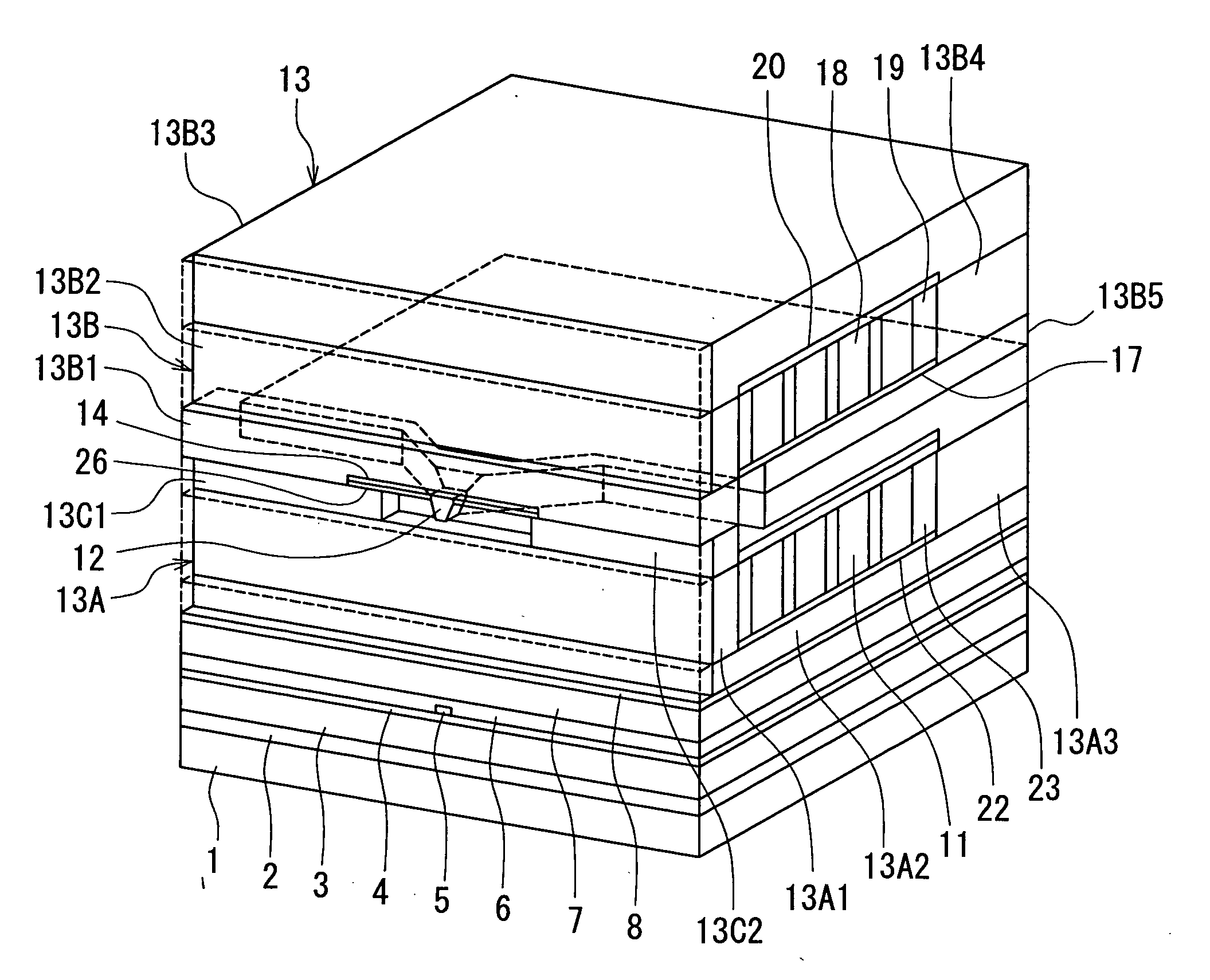
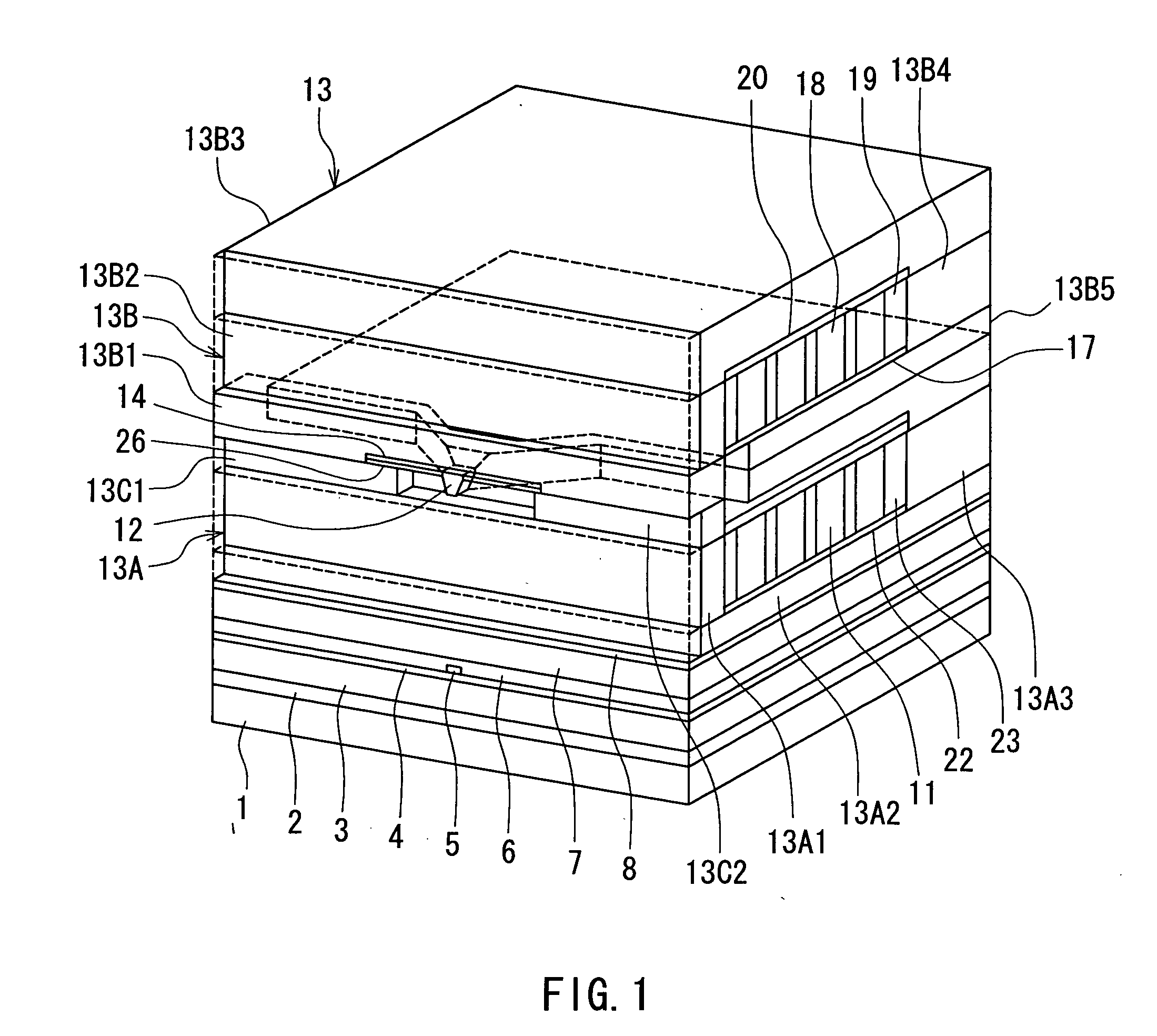
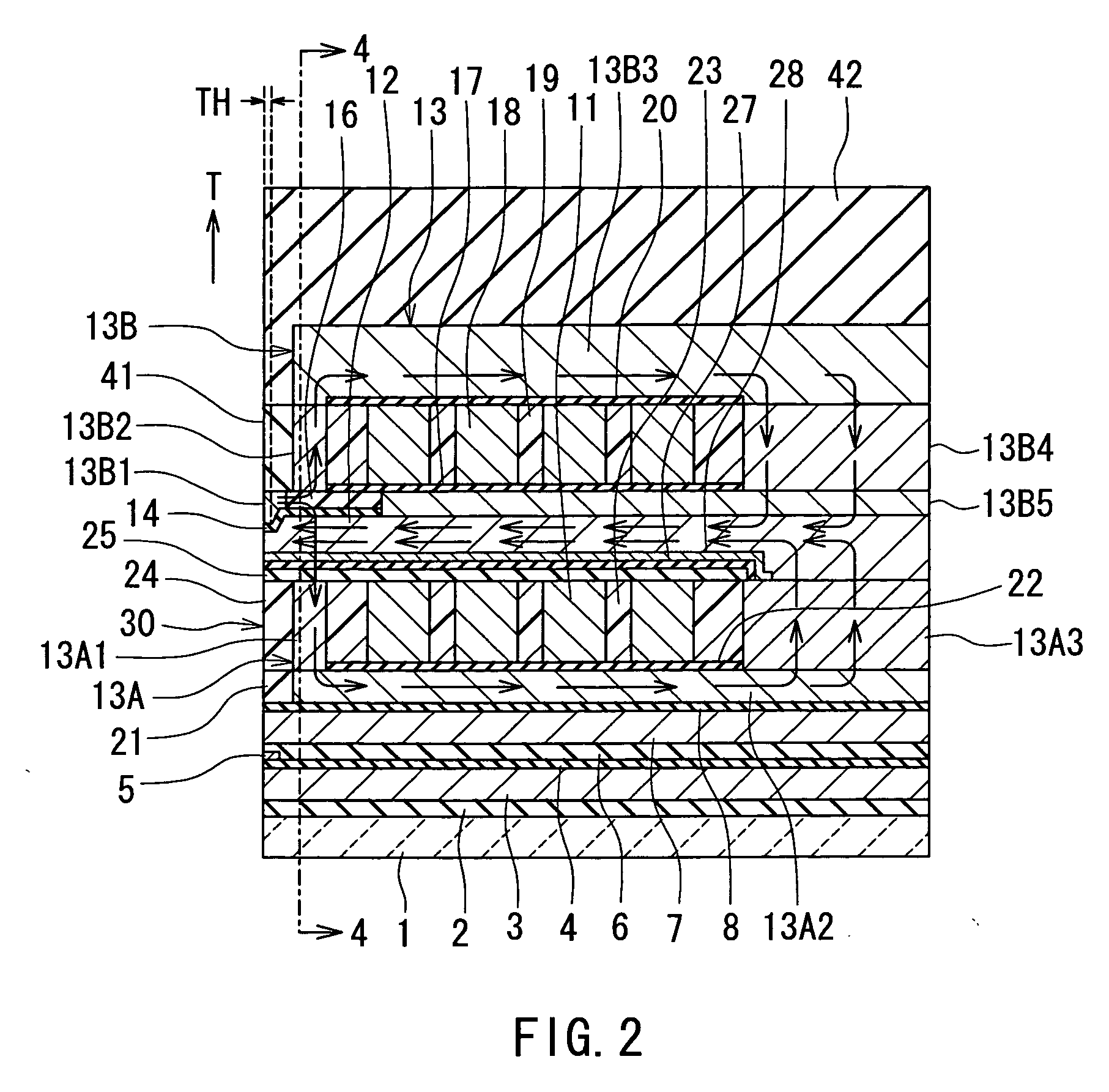
[0075]Preferred embodiments of the invention will now be described in detail with reference to the accompanying drawings. Reference is now made to FIG. 1 to FIG. 5 to describe the configuration of a magnetic head for perpendicular magnetic recording of a first embodiment of the invention. FIG. 1 is a perspective view illustrating a portion of the magnetic head of the first embodiment in a neighborhood of the medium facing surface. FIG. 2 is a cross-sectional view for illustrating the configuration of the magnetic head of the embodiment. FIG. 2 illustrates a cross section orthogonal to the medium facing surface and the plane of a substrate. The arrow indicated with T in FIG. 2 shows the direction of travel of a recording medium. FIG. 3 is a front view of the medium facing surface of the magnetic head of the embodiment. FIG. 4 is a cross-sectional view taken along line 4-4 of FIG. 2. FIG. 5 is a top view for illustrating a pole layer and a shield of the magnetic head of the embodiment...

second embodiment

[0160]Reference is now made to FIG. 18 to describe a magnetic head and a method of manufacturing the same of a second embodiment of the invention. FIG. 18 is a cross-sectional view for illustrating the configuration of the magnetic head of the second embodiment. FIG. 18 illustrates a cross section orthogonal to the medium facing surface and the plane of the substrate. The arrow indicated with T in FIG. 18 shows the direction of travel of a recording medium.

[0161]In the magnetic head of the second embodiment, the insulating layer 19 is provided to cover the coil 18. In the second embodiment the insulating layers 20 and 41 of the first embodiment are not provided. The second portion 13B of the shield 13 of the second embodiment incorporates a first layer 13B21, a second layer 13B22 and an upper yoke layer 13B23. These layers may be made of any of CoFeN, CoNiFe, NiFe and CoFe, for example. The shapes and locations of the first layer 13B21 and the upper yoke layer 13B23 are the same as ...

third embodiment

[0164]Reference is now made to FIG. 19 to describe a magnetic head and a method of manufacturing the same of a third embodiment of the invention. FIG. 19 is a cross-sectional view for illustrating the configuration of the magnetic head of the third embodiment. FIG. 19 illustrates a cross section orthogonal to the medium facing surface and the plane of the substrate. The arrow indicated with T in FIG. 19 shows the direction of travel of a recording medium.

[0165]The second portion 13B of the shield 13 of the third embodiment incorporates a first layer 13B31, a second layer 13B32, a third layer 13B33, a fourth layer 13B34, a fifth layer 13B35, a sixth layer 13B36, and an upper yoke layer 13B37. These layers may be made of any of CoFeN, CoNiFe, NiFe and CoFe, for example. The shapes and locations of the first layer 13B31 and the upper yoke layer 13B37 are the same as those of the first layer 13B1 and the upper yoke layer 13B5 of the first embodiment, respectively.

[0166]The second layer ...


PUM


Abstract

A magnetic head comprises a pole layer, a first coil, a second coil, and a shield. The shield incorporates: a first portion located backward of the pole layer along the direction of travel of a recording medium; a second portion located forward of the pole layer along the direction of travel of the recording medium; and two coupling portions. The first portion has an end face located in a medium facing surface. The two coupling portions couple the first and second portions to each other without touching the pole layer. Part of the first coil passes through a space surrounded by the pole layer and the first portion. Part of the second coil passes through a space surrounded by the pole layer and the second portion.

Description

BACKGROUND OF THE INVENTION[0001]1. Field of the Invention[0002]The present invention relates to a magnetic head for perpendicular magnetic recording that is used for writing data on a recording medium by means of a perpendicular magnetic recording system and to a method of manufacturing such a magnetic head.[0003]2. Description of the Related Art[0004]The recording systems of magnetic read / write devices include a longitudinal magnetic recording system wherein signals are magnetized in the direction along the surface of the recording medium (the longitudinal direction) and a perpendicular magnetic recording system wherein signals are magnetized in the direction orthogonal to the surface of the recording medium. It is known that the perpendicular magnetic recording system is harder to be affected by thermal fluctuation of the recording medium and capable of implementing higher linear recording density, compared with the longitudinal magnetic recording system.[0005]Like magnetic heads...

Claims


Application Information

Patent Timeline
IPC IPC(8): G11B5/127
CPCG11B5/112G11B5/1278G11B5/3116G11B5/3123G11B5/23G11B5/3163G11B5/3169G11B5/315G11B5/3136
Inventor SASAKI, YOSHITAKAITOH, HIROYUKITANEMURA, SHIGEKISHIMIZU, TATSUSHISHIMIZU, TATSUYA
Owner HEADWAY TECH INC
Why Eureka
Try Eureka