
Deconding device and decoding method

a decoding device and decoding technology, applied in the field of arithmetic circuits, can solve problems such as high correction capability for error correction codes, significant increase in circuit size, and problems in actual applications, and achieve the effect of reducing the degradation of the correction capability of log maps

Inactive Publication Date: 2008-04-17
RENESAS ELECTRONICS CORP
View PDF10 Cites 24 Cited by
  • Summary
  • Abstract
  • Description
  • Claims
  • Application Information

AI Technical Summary

Benefits of technology

The present invention provides a decoding device and method that can improve the correction capability of a Log-MAP decoder. This is achieved by calculating a path metric value for received data and adjusting its degree of correction based on the data being decoded. This can reduce degradation in the decoder's correction ability, resulting in improved data decoding accuracy.

Problems solved by technology

Particularly in mobile communication systems where the radio field intensity varies drastically due to fading and thereby an error is likely to occur, high correction capability is required for error correcting codes.
As described above, the MAP algorithm calculates the product of the probabilities and therefore it requires a multiplier, which causes a significant increase in circuit size.
However, Expressions 10 and 11 contain the items that the replacement of the calculation inside the parentheses exp. with Ai results in Expression 12 below, which poses a problem in actual applications.
However, in the operation in the Log-MAP, the coefficient of the SNR (Eb / No) cannot be ignored.
In such a case, it is reported that the correction capability is degraded when the error between the estimation value and the actual SNR is large, which occasionally may reverse the correction capability between Log-MAP and Max-Log-MAP depending on conditions.
However, in the method described in Alexander WORM et al. and in Mohammad Ali Khalighi the operation of the SNR estimation and the operation using the estimated SNR are needed, which increase an amount of the operation and the process time.
However, the estimation is quite difficult because there are many kinds of noise and an optimal SNR estimation algorithm varies depending on the operational system.SNR=10 log (PS / PN),PN indicates a noise power [W], andPS indicates a signal power [W].
In addition, in the method described in Alexander WORM et al., the error correction capability is degraded depending on conditions if the SNR estimation is not performed.
It is true that the degradation of the correction capability also occurs by the SNR estimation error as well.
However, the correction capability can be degraded because this method employs the Max-Log-MAP at the first time.
However, there are many kinds of noise, so it is difficult to select the optimal SNR estimation algorithm.
Therefore, the SNR estimation is quite difficult.
In addition, it is needed to estimate the SNR in advance, which causes the overhead process and delays the process time.
Moreover, the performance of the error correction is degraded when the SNR error is large.

Method used


Image

  • Deconding device and decoding method
  • Deconding device and decoding method
  • Deconding device and decoding method

Examples


Embodiment Construction

[0088]The invention will be now described herein with reference to illustrative embodiments. Those skilled in the art will recognize that many alternative embodiments can be accomplished using the teachings of the present invention and that the invention is not limited to the embodiments illustrated for explanatory purposes.

[0089]A specific embodiment to which the present invention is applied will be described in detail below with reference to the drawings. The present embodiment is the one in which the present invention is applied to a turbo decoding device employing a Log-MAP algorithm.

[0090]As described above, the Log-MAP needs a value of SNR (Eb / No) for operation as shown in the Expressions 6, 16, and 17. However, there are many kinds of noise, and an optimal SNR estimation algorithm varies depending on operational systems. Therefore, estimating the SNR is not easy.

[0091]In the present embodiment, a fixed value is used for the SNR. The value of the SNR can be determined based on...


PUM


Abstract

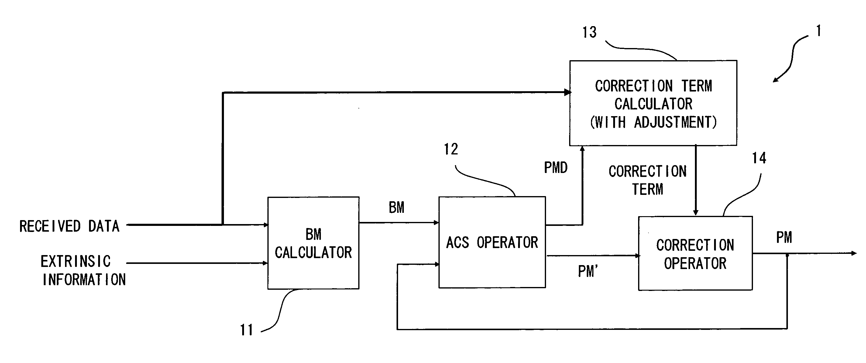
A decoding device includes a BM calculator calculating a branch metric in a Log-MAP algorithm from received data and extrinsic information, an ACS operator calculating a maximum value of a path metric based on the branch metric, a correction term calculator calculating a Jacobian correction value of the path metric, and a correction operator correcting the path metric by adjusting a value of the Jacobian correction value based on a size of the received data and adding the adjusted correction value to the maximum value.

Description

BACKGROUND OF THE INVENTION[0001]1. Field of the Invention[0002]The present invention relates to an arithmetic circuit for correcting an approximate value that is computed by the Max-Log-MAP algorithm based on the Log-MAP algorithm.[0003]2. Description of Related Art[0004]In digital communications system, an error correcting code for correcting an error occurring in a transmission line is used. Particularly in mobile communication systems where the radio field intensity varies drastically due to fading and thereby an error is likely to occur, high correction capability is required for error correcting codes. Turbo codes, which are one example of error correcting codes, are notable as the codes having the error correction capability which is close to the Shannon limit and employed in the W-CDMA (Wideband Code Division Multiple Access) or CDMA-2000 as the third-generation mobile communication system, for example.[0005]FIG. 8 is a block diagram showing the structure of a typical encodi...

Claims


Application Information

Patent Timeline
Patent Type & Authority Applications(United States)
IPC IPC(8): H03M13/37G06F11/07
CPCH03M13/2957H03M13/658H03M13/3911
Inventor ORIO, MASAO
Owner RENESAS ELECTRONICS CORP
Learn More