Thermal mass flow meter

a technology of mass flow meter and mass flow, which is applied in the direction of volume/mass flow measurement, measurement devices, instruments, etc., can solve the problems of high manufacturing cost and inability to achieve low cost, and achieve the effect of improving measuring performan

Active Publication Date: 2008-04-24
SHIMADZU CORP
View PDF9 Cites 27 Cited by
  • Summary
  • Abstract
  • Description
  • Claims
  • Application Information

AI Technical Summary

Benefits of technology

[0009]An objective of the present invention is to improve me

Problems solved by technology

However, the process for assembling the heat generating element 32 and the paired temperature sensors 34 onto a single

Method used


Image

  • Thermal mass flow meter
  • Thermal mass flow meter
  • Thermal mass flow meter

Examples


Embodiment Construction

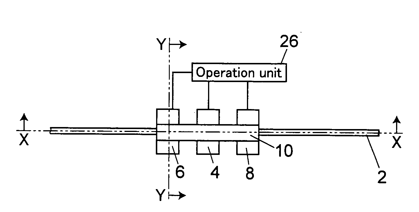
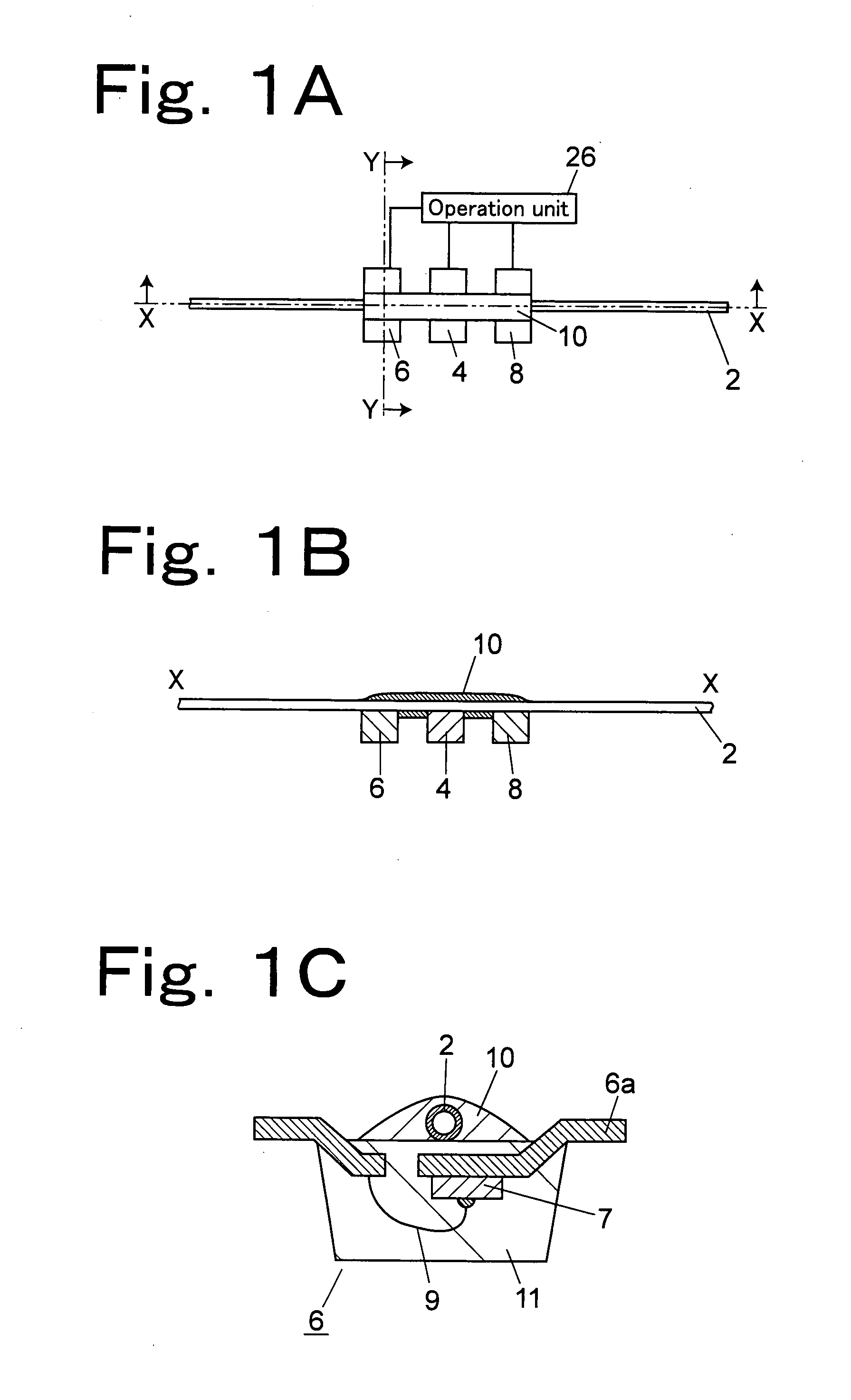
[0024]FIGS. 1A to 1C are views that show a thermal mass flow meter in accordance with one embodiment, FIG. 1A is a plan view, FIG. 1B is a cross-sectional view taken along line X-X of FIG. 1A, and FIG. 1C is a cross-sectional view taken along line Y-Y of FIG. 1A.

[0025]A heater chip 4 serving as a heat generating element is placed on a lower side of a capillary 2 serving as piping used for fluid-transporting a minute sample, in a manner so as to be touching therewith. Here, based upon the state shown in FIG. 1B, the “lower side” is defined; however, the present embodiment is not intended to be limited by this layout. The capillary 2 may be placed in a perpendicular direction, and in this case also, a side having a convex portion of each of elements 4, 6 and 8 on a side opposite to the capillary 2 is referred to as the lower side. With respect to the heater chip 4, for example, a chip diode ISS387 (product made by Toshiba Corp.) and a chip resistor RK73H1JT (product made by Koa Corpor...


PUM


Abstract

A piping is anchored onto the lower faces of a heater chip and temperature sensor chips by using a thermal conductive adhesive. The heater chip and the temperature sensor chips are coated with a molding resin, and thermal resistance up to an element formed inside thereof is made smallest on a lower face side.

Description

BACKGROUND OF THE INVENTION[0001]1. Field of the Invention[0002]This invention relates to a thermal mass flow meter that measures a mass flow rate of a fluid flowing through a piping based upon a temperature distribution of the fluid in a flowing direction of the fluid.[0003]2. Description of the Related Art[0004]Referring to FIGS. 5A and 5B, the following description will discuss a conventional thermal mass flow meter. FIG. 5A is a cross-sectional view and FIG. 5B is a graph that shows a temperature distribution on a surface of a piping. In FIG. 5B, the axis of abscissas represents the position in a flowing direction, and the axis of ordinates represents the temperature. A curved line, indicated as a broken line, represents the temperature distribution in a state with no fluid flowing through the piping, and a curved line, indicated by a solid line, represents the temperature distribution in a state with a fluid flowing through the piping.[0005]As shown in FIG. 5A, a heater 32 is s...

Claims


Application Information

Patent Timeline
IPC IPC(8): G01F1/68
CPCG01F1/696G01F1/6847
Inventor HASEBE, SHINYA
Owner SHIMADZU CORP
Why Eureka
Try Eureka