Combustion Control Device

a control device and combustion technology, applied in combustion regulation, combustion measurement, combustion failure safe, etc., can solve the problems of excessive combustion or accidental extinction, deterioration of the combustion state, etc., to improve the compatibility of components, reduce the risk of failure, and improve the effect of safety

Active Publication Date: 2008-04-24
NORITZ CORP +1
View PDF2 Cites 23 Cited by
  • Summary
  • Abstract
  • Description
  • Claims
  • Application Information

AI Technical Summary

Benefits of technology

[0059] The combustion control device in the present invention allows a sub microcomputer with lower capability to be employed, thereby improving the

Problems solved by technology

Thus, if and when the microcomputer runs out of control, fuel gas supply or air blow goes out of control, resulting in excessive combustion or acciden

Method used


Image

  • Combustion Control Device
  • Combustion Control Device
  • Combustion Control Device

Examples


Embodiment Construction

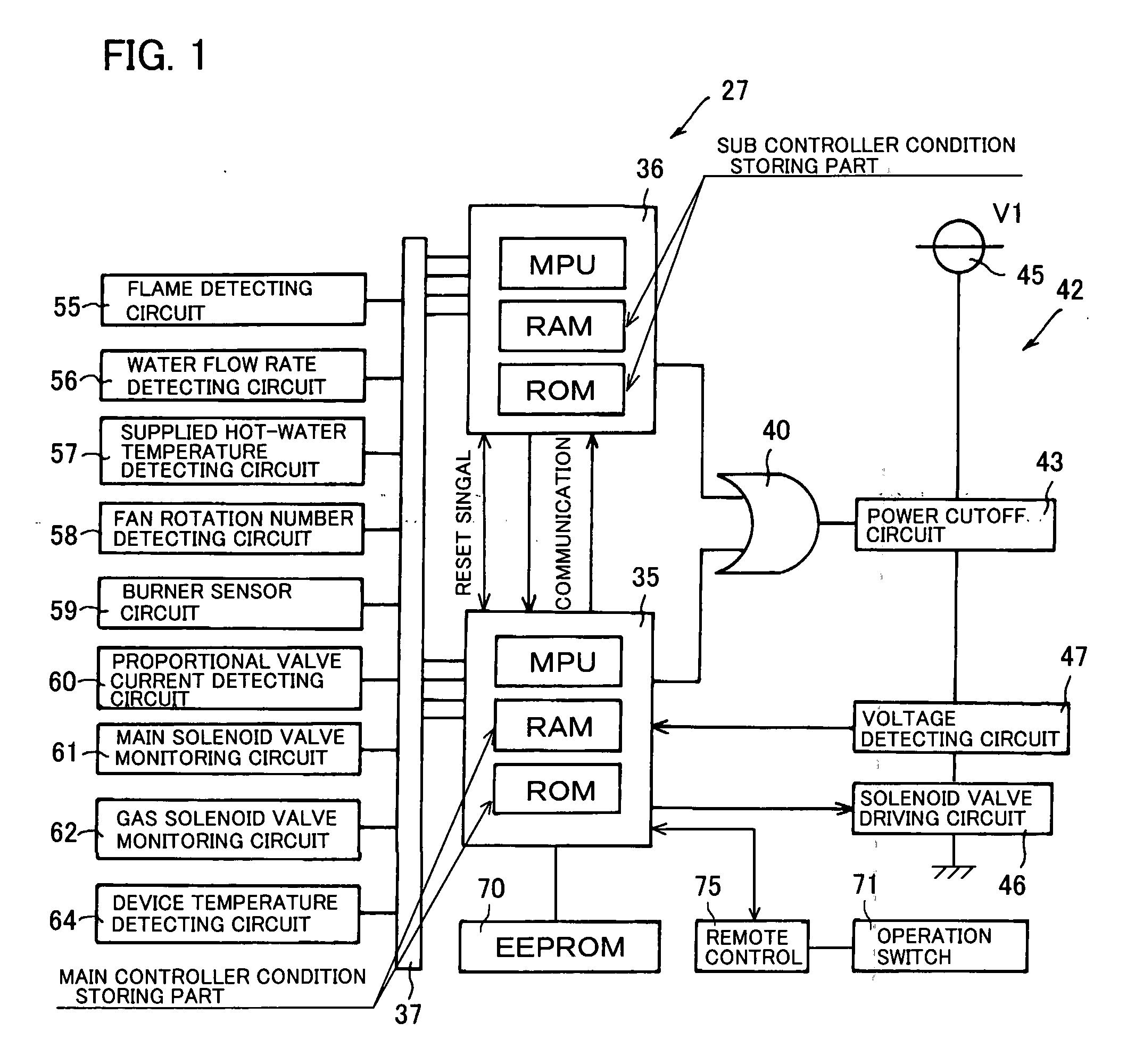
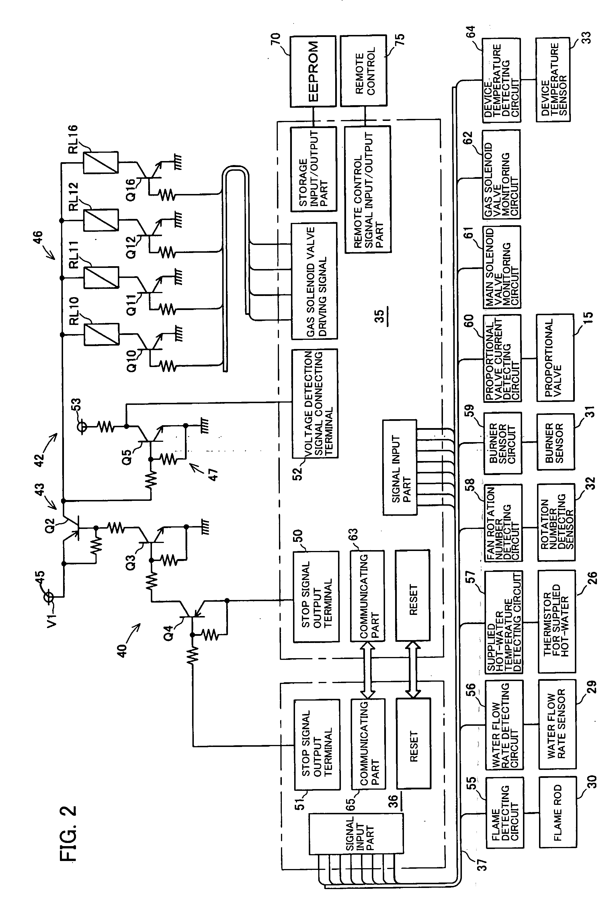
[0065] Now, an embodiment of the present invention will be described below in detail, making reference to the accompanying drawings.

[0066] A combustion control device 27 in the present embodiment is used in a water heater 1 as shown in FIG. 3. The water heater 1 runs on gas, which is supplied to a burner group 2, so as to burn the gas. The water heater 1 in the present embodiment has three burners 5, 6, and 7 and gas solenoid valves 10, 11, and 12 located at their respective gas supply passages, respectively.

[0067] The gas supply passages are united into one passage to be connected to a gas supply source 13, a proportional valve 15 and a main solenoid valve 16 intervening therebetween. The gas solenoid valves 10, 11, and 12 and the main solenoid valve 16 are normally-closed valves and closed upon cutoff of electric current supply to solenoids.

[0068] The water heater 1 has a heat exchanger 18 and is for heating water in the heat exchanger 18 by flame generated in the burner group ...


PUM


Abstract

The present invention relates to a combustion control device incorporated in an apparatus such as water heater and provides the combustion control device having an improved configuration with a main controller and a sub controller, capable of employing a microcomputer with lower capability as the sub controller, and ensuring higher safety than ever before.
Signals indicating a combustion state of a combustion apparatus are inputted into the main controller 35 and the sub controller 36 in parallel. Upon fulfillment of a predetermined condition of stopping, the main and sub controllers 35 and 36 each output a stop signal to cut off a current to be supplied to a device driving circuit 42. The conditions of stopping in outputting of the stop signal by the main and sub controllers are such that the sub controller 36 is less apt to execute the cutoff than the main controller 35.

Description

BACKGROUND OF THE INVENTION [0001] 1. Field of the Invention [0002] The present invention relates to a control device for a combustion apparatus. The present invention is suitable for a control device for combustion apparatus provided with a hot water supply function. [0003] 2. Description of Related Art [0004] Combustion apparatus as typified as a gas water heater has a control device equipped in its controlling center with a microcomputer, whereby operational control on various actuators such as a gas solenoid valve for switching supply / stop of fuel gas, a proportional valve for adjusting fuel gas supply, a fan motor for adjusting combustion air blow. [0005] Thus, if and when the microcomputer runs out of control, fuel gas supply or air blow goes out of control, resulting in excessive combustion or accidental extinction. Further, that might cause a fan out of control, resulting in deterioration of a combustion state due to disproportion of air-fuel ratio. Therefore, a means for de...

Claims


Application Information

Patent Timeline
IPC IPC(8): F24H9/20
CPCF23N5/242F23N2025/02F23N2025/16F23N2041/04F23N2031/06F23N2031/12F23N2025/19F23N2225/02F23N2225/16F23N2225/19F23N2231/06F23N2231/12F23N2241/04
Inventor KISHIMOTO, TOMOKITAKAGI, YUJIYASUKAWA, MASAYOSHITAKABAYASHI, AKIRAOKAMOTO, SHINICHIYOKOYAMA, HIROSHIYASHIMA, TAKASHIKUBOTANI, MASANORI
Owner NORITZ CORP
Why Eureka
Try Eureka