Methods and apparatus for latch-up free boosting

a technology of latch-up and free boosting, which is applied in the direction of logic circuit coupling/interface arrangement, process and machine control, instruments, etc., can solve the problems of permanent destruction of chips including the cmos structure, large current produced,

Inactive Publication Date: 2008-04-24
SAMSUNG ELECTRONICS CO LTD
View PDF4 Cites 29 Cited by
  • Summary
  • Abstract
  • Description
  • Claims
  • Application Information

AI Technical Summary

Benefits of technology

[0009] It is therefore a separate feature of an embodiment of the present invention to provide a voltage generator tha...

Problems solved by technology

Depending on the circuitry, the amount of current produced may be large enough to permanen...

Method used


Image

  • Methods and apparatus for latch-up free boosting
  • Methods and apparatus for latch-up free boosting
  • Methods and apparatus for latch-up free boosting

Examples


Embodiment Construction

[0032] Korean Patent Application No. 10-2006-95920, filed on Sep. 29, 2006, in the Korean Intellectual Property Office, and entitled: “Latch-Up Free Boosting Scheme,” is incorporated by reference herein in its entirety.

[0033] Embodiments of the present invention will now be described more fully hereinafter with reference to the accompanying drawings, in which exemplary embodiments of the invention are illustrated. Embodiments of the invention may, however, be embodied in different forms and should not be construed as limited to the exemplary embodiments set forth herein. Rather, these exemplary embodiments are provided so that this disclosure will be thorough and complete, and will fully convey the scope of the invention to those skilled in the art.

[0034] In the figures, the dimensions of layers and regions may be exaggerated for clarity of illustration. It will also be understood that when an element is referred to as being connected to another element or between two elements, th...


PUM


Abstract

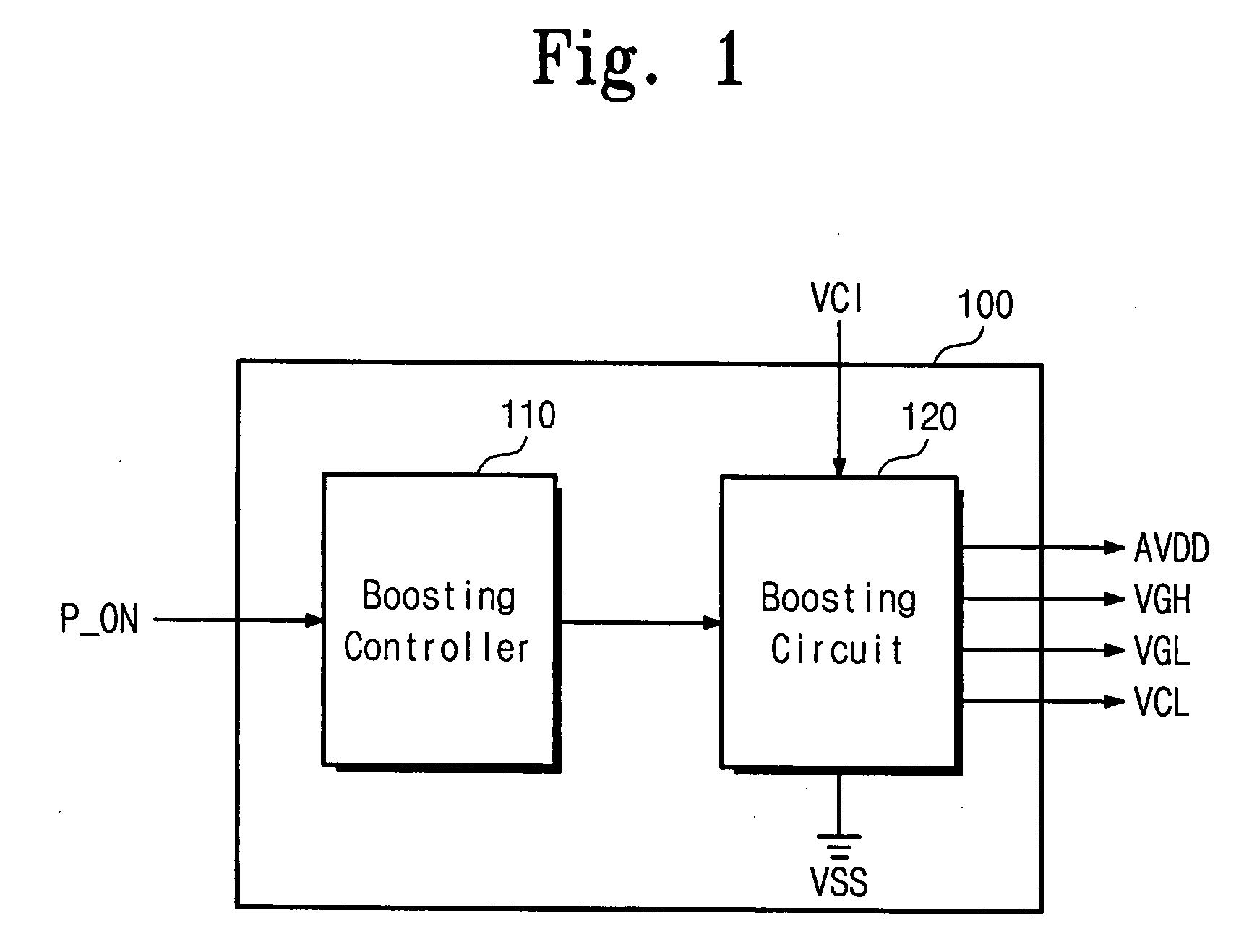
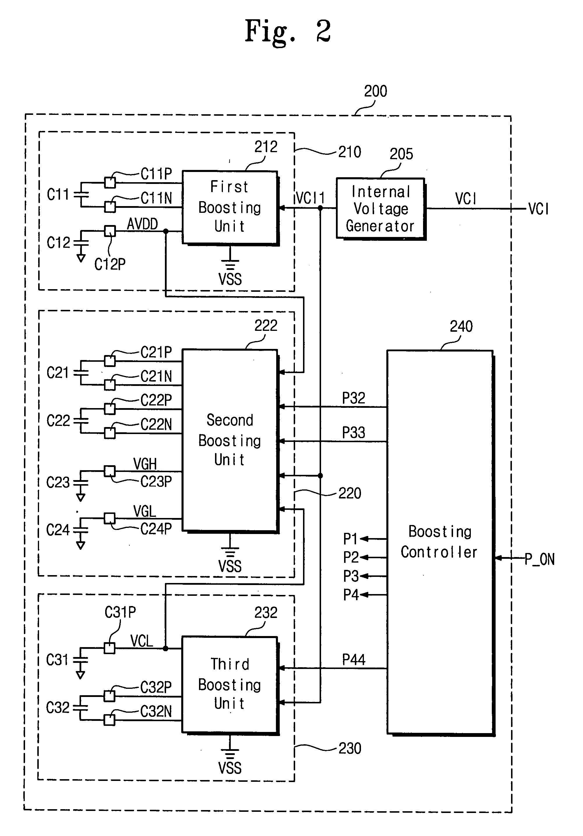
A voltage generator includes a boosting circuit boosting a power voltage to generate first through fourth voltages, and a boosting controller controlling the boosting circuit. The boosting controller sets the third and fourth voltages to a voltage level lower than that of a ground voltage while the first and second voltages are generated, so that a plurality of voltages may be stably generated, i.e., without latch-up.

Description

BACKGROUND OF THE INVENTION [0001] 1. Field of the Invention [0002] Embodiments of the present invention relate to methods and apparatus for boosting a voltage when power is turned on (“power-on”). More particularly, embodiments of the invention relate to latch-up free voltage boosting methods and apparatuses for stably boosting voltages without triggering latch-up. [0003] 2. Description of the Related Art [0004] Generally, a peculiar state called latch-up may occur in a device having a complementary metal oxide semiconductor (CMOS) structure. Latch-up is a parasitic phenomenon that may occur when a parasitic thyristor, e.g., silicon controlled rectifier (SCR), at a PNPN junction inherently existing in a CMOS chip causes over-current to flow. Depending on the circuitry, the amount of current produced may be large enough to permanently destroy a chip including the CMOS structure. Latch-up generally occurs when input and output voltages exceed a rated level so that large current flows...

Claims


Application Information

Patent Timeline
IPC IPC(8): G09G3/36G05F3/08
CPCG09G3/3648G09G3/3696G09G2330/02G02F1/13306H02M3/07H02M2001/009G09G2330/04H02M1/009G09G2330/026H03K5/02H03K19/0175
Inventor PARK, JAE-HOKANG, WON-SIK
Owner SAMSUNG ELECTRONICS CO LTD
Why Eureka
Try Eureka