
System For The Three-Dimensional Imaging Of A Moving Joint

a three-dimensional imaging and joint technology, applied in the field of systems and methods for the generation of three-dimensional images of joints, can solve the problems of substantially different movements of joints, and achieve the effect of high information

Inactive Publication Date: 2008-04-24
KONINKLIJKE PHILIPS ELECTRONICS NV
View PDF6 Cites 133 Cited by
  • Summary
  • Abstract
  • Description
  • Claims
  • Application Information

AI Technical Summary

Benefits of technology

[0003] Based on this situation it was an object of the present invention to provide means for an accurate and highly informative analysis of joint movements.
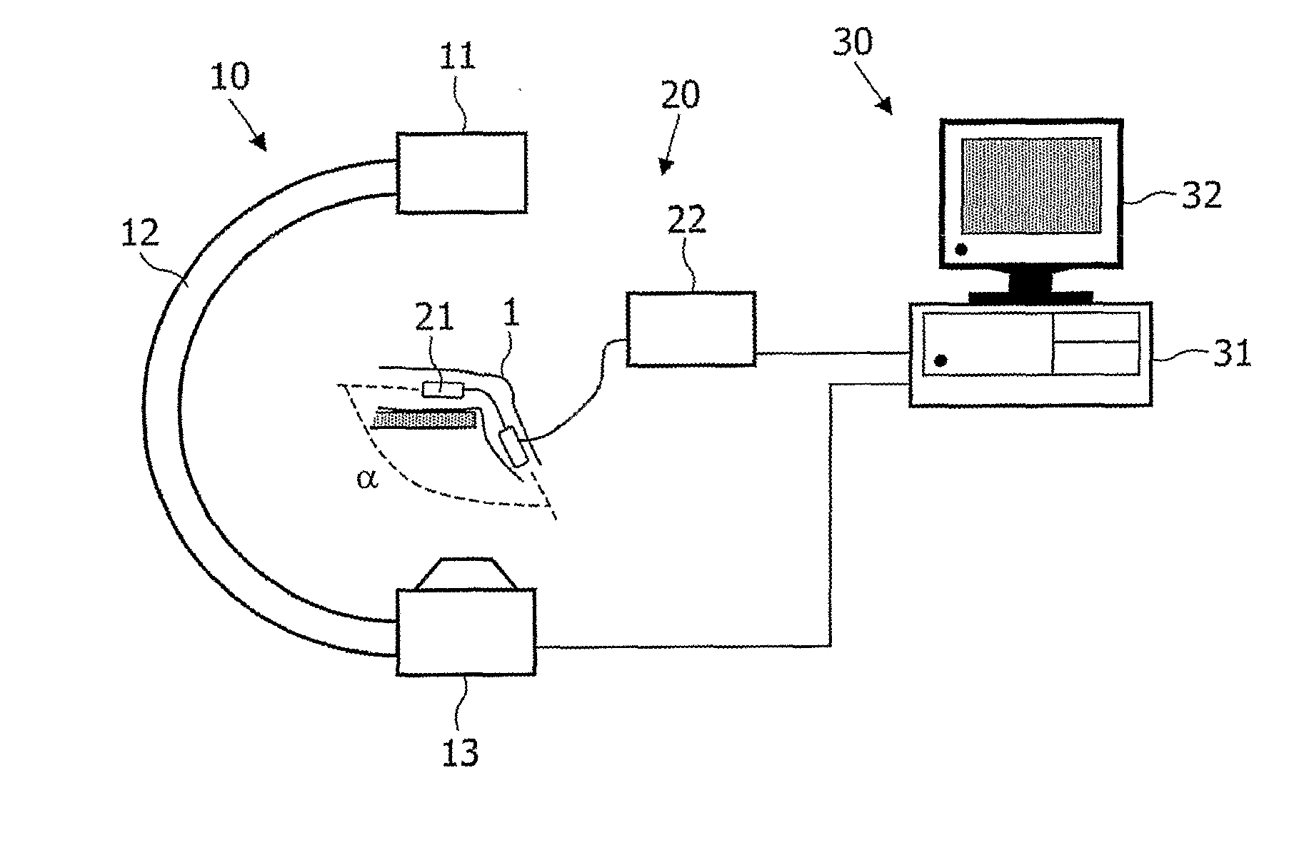
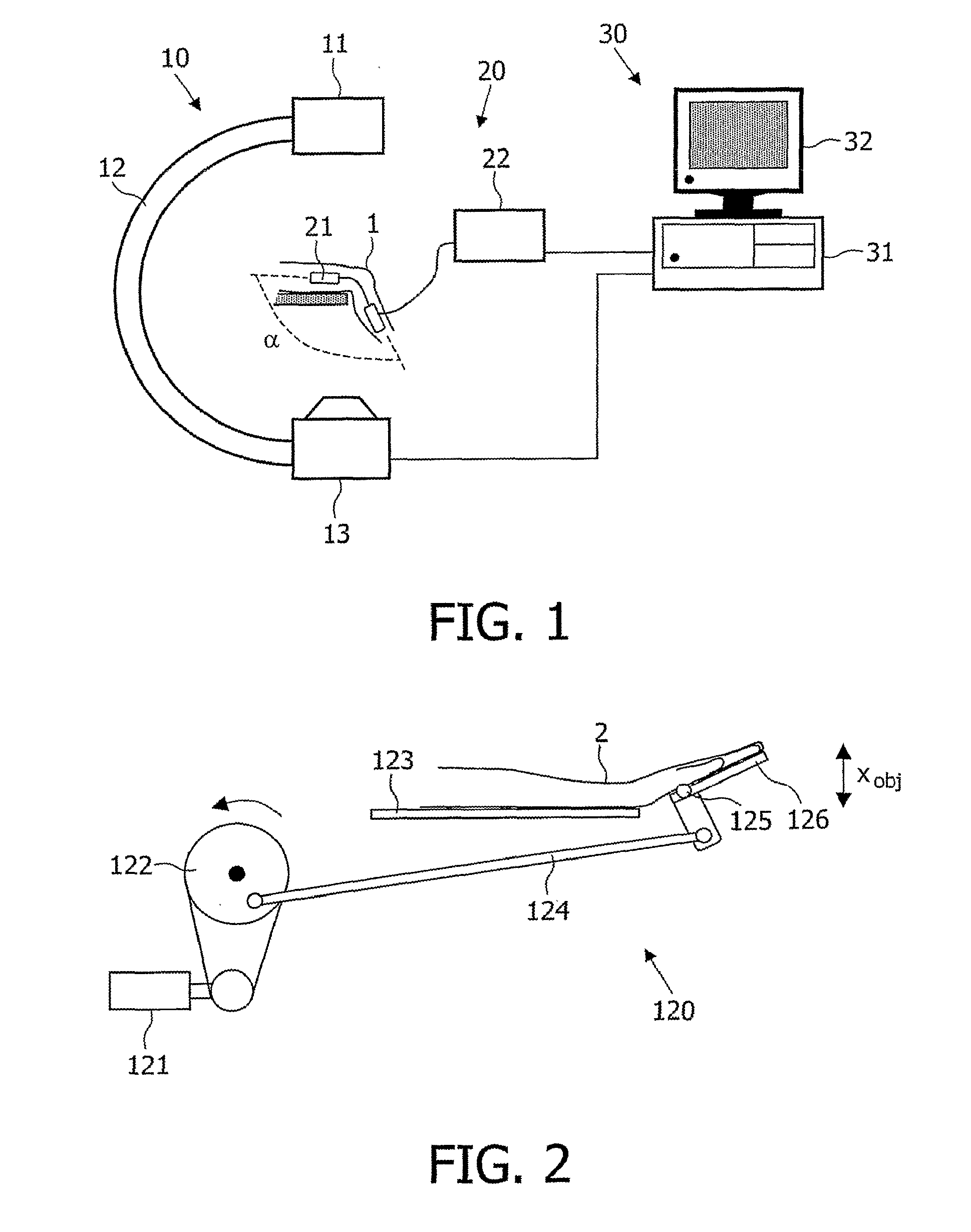
[0009] The system described above has the advantage that it allows the generation of a 3D film sequence of the joint movement which has a high correlation to the actual movement because it is based on real 3D images of the joint. Moreover, the generation of such a movie is possible with a rotational X-ray device which is already present as a standard equipment in many medical laboratories.
[0013] The aforementioned embodiments of the monitoring device provide information on the current joint motion phase by measuring it. According to another embodiment, the monitoring device comprises an apparatus that is adapted to force an externally prescribed movement on the joint. Said apparatus may for example comprise a static and a movable support which are connected by a link, wherein the movable support can be periodically pivoted with respect to the static support by some motor device. If then two segments of a joint, for example upper arm and forearm, are placed on the different supports, the corresponding joint will follow the prescribed movement of the supports (provided that the force of the apparatus is strong enough). A monitoring device of this kind has the advantage that the movement of the joint can be externally prescribed and must not the generated by the patients themselves. This guarantees a high accuracy and reproducibility of the movement with selectable parameters (for example frequency). Moreover, the investigation can be made even if the patient is unconscious or the respective joint is paralyzed. The monitoring device provides information on the current motion phase of the joint implicitly (without measurements) by guaranteeing that a known movement with e.g. a prescribed frequency is carried out.
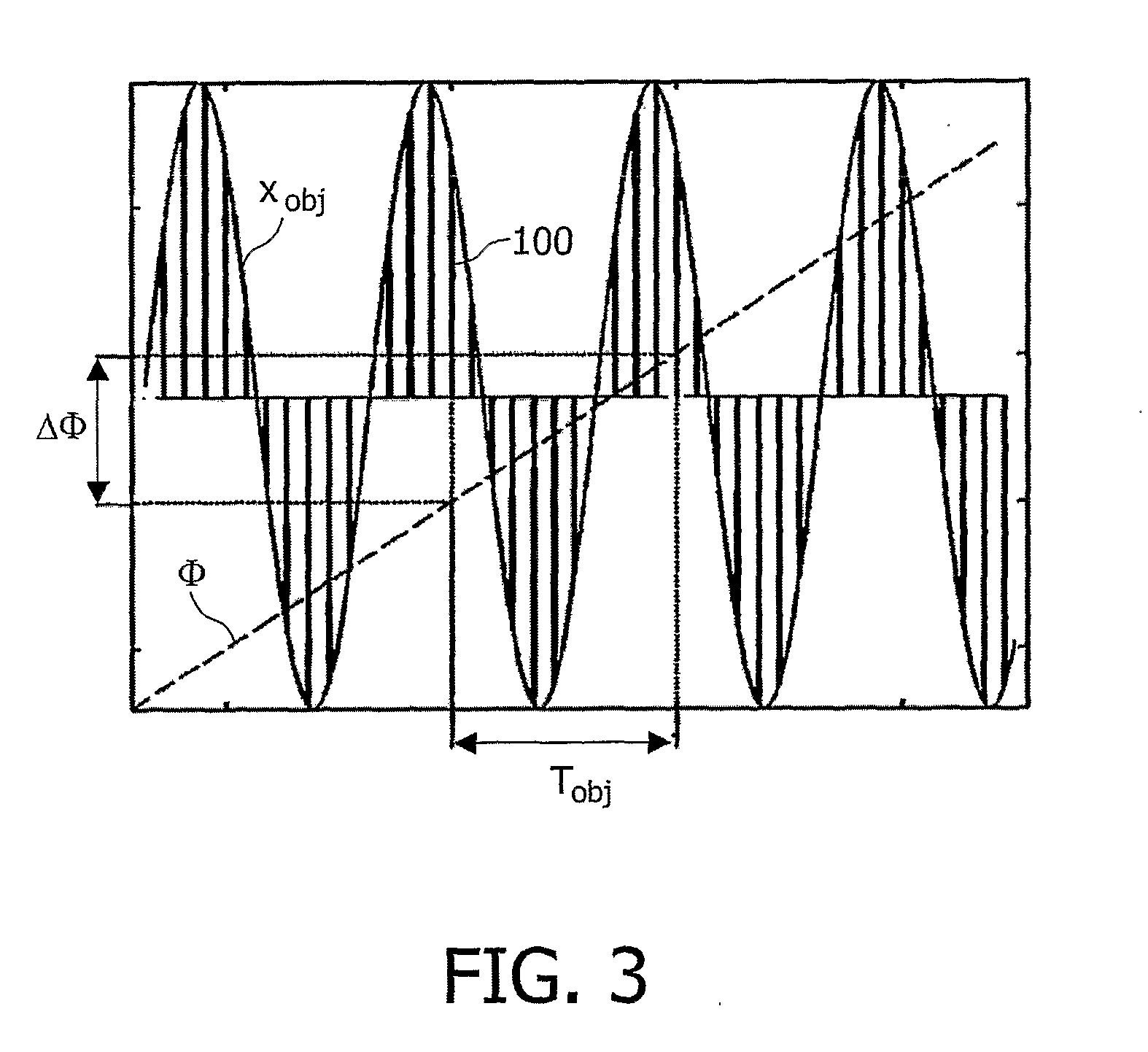
[0014] In a preferred embodiment of the invention, the system is adapted such that the movement of the joint is synchronized with the generation of projections by the X-ray device. In particular, the frequency of the generation of X-ray projections may be an integer multiple of the frequency of a periodic joint movement. Such a synchronization guarantees that a plurality of X-ray projections is generated for the same relative phases of the joint movement. The reconstruction of 3D images for such phases is then possible with high accuracy. The synchronization of joint movement and image generation may for example be achieved by prompting an X-ray projection each time a certain motion phase of the joint is passed. Moreover a synchronization may readily be achieved if an apparatus of the aforementioned kind for a forced external movement of the joint is used.
[0018] According to a preferred embodiment of the method, the joint is actively moved in synchronization with the generation of X-ray projections. An active movement of the joint guarantees a high accuracy and reproducibility of its movement, whereas the synchronization of joint movement and X-ray projections guarantees a repeated imaging of the same phases of joint movement.

Problems solved by technology

The actual joint movement may however differ substantially from such a movie because the latter relies on a plurality of assumptions and because positional errors are introduced by the registration of 2D projections with 3D representations.

Method used


Image

  • System For The Three-Dimensional Imaging Of A Moving Joint
  • System For The Three-Dimensional Imaging Of A Moving Joint
  • System For The Three-Dimensional Imaging Of A Moving Joint

Examples


Embodiment Construction

[0025] Proper functioning of the wrist joint is essential in performing manual tasks ranging from personal care activities to computer related tasks. In case of a malfunctioning wrist it is of major importance for the patient and the doctor to recognize and properly diagnose problems in the wrist at an early stage. To judge wrist function the analysis of 3D patterns of movement of the carpal bones in the wrist joint are crucial. Current 3D imaging methods allow static detection of carpal bone positions and orientations. State of the art detection of 3D carpal bone positions and orientations at multiple poses of the hand can provide for an animated movement pattern only. However, from 2D video radiographic observations it is known that clinically significant abrupt changes in orientation and position of carpal bones can occur. These abrupt changes cannot be detected from the limited number of poses that can be achieved with a 3D static imaging method. Moreover, a real time dynamic mo...


PUM


Abstract

The invention relates to a system and a method for the generation of 3D images of a moving joint (1). A rotational X-ray device (10) generates projections of said joint from different directions while the simultaneous periodic movement of the joint (1) is recorded by a monitoring device (20). The generated X-ray projections are then classified according to the phase of joint movement to which they belong, and 3D images are reconstructed from X-ray projections of each class. Thus a 3D movie of the joint movement can be produced and shown on a monitor. The monitoring device (20) may particularly be realized by an apparatus that allows the forced movement of the joint (1) in synchronization with the generation of X-ray projections.

Description

FIELD OF THE INVENTION [0001] The invention relates to a system and a method for the generation of three-dimensional images of a joint in different phases of its motion. BACKGROUND OF THE INVENTION [0002] X-ray images are an important tool for the analysis and diagnosis of the (mal-)function of body joints. For an investigation of the movement of the knee it was proposed in literature to generate a three-dimensional (3D) model of the joint by computer tomography (CT) first and then to record a joint movement by X-ray projections taken simultaneously from two different directions (B. You, P. Siy, W. Anderst, S. Tashman: “In Vivo Measurement of 3-D Skeletal Kinematics from Sequences of Biplane Radiographs: Application to Knee Kinematics”, IEEE Transactions on Medical Imaging, pp. 514-525 (2001)). Parameters derived from said X-ray projections are used in this approach as input to the 3D joint model for the generation of a 3D movie. The actual joint movement may however differ substant...

Claims


Application Information

Patent Timeline
IPC IPC(8): G06K9/00G06T17/00
CPCA61B5/4528A61B5/7264A61B6/4441A61B6/466G06T2211/412A61B6/541G06T11/005G06T2210/41A61B6/505
Inventor SABCZYNSDI, JOERGSTREEKSTRA, GEERT
Owner KONINKLIJKE PHILIPS ELECTRONICS NV
Learn More