Wire grid polarized and liquid crystal display device using the same

a technology of liquid crystal display device and wire grid, which is applied in the direction of polarising elements, instruments, optics, etc., can solve the problems of low contrast in brightly illuminated ambience, degrade image quality, and inferior performance of ordinary polarizers, so as to reduce thickness and the cost of lcd devices of transmission or transflective types, the effect of increasing display brightness

Active Publication Date: 2008-04-24
PANASONIC LIQUID CRYSTAL DISPLAY CO LTD +1
View PDF9 Cites 119 Cited by
  • Summary
  • Abstract
  • Description
  • Claims
  • Application Information

AI Technical Summary

Benefits of technology

[0014]This invention is intended to be applied to a LCD device having transmission display sections. According to this invention, the thickness and the cost of an LCD device of transmission type or transflective type can be reduced whil...

Problems solved by technology

However, if the disclosed configuration is used in the LCD device having a light transmission section, a problem arises that contrast is lowered in a brightly illuminated ambience due to the polarized light reflected from the wire grid polarizer.
However, there will arise a problem that in the brightly illuminated ambience the image quality is degraded due to the degradation of contrast caused by the reflection of ambience light.
However, such a coatin...

Method used


Image

  • Wire grid polarized and liquid crystal display device using the same
  • Wire grid polarized and liquid crystal display device using the same
  • Wire grid polarized and liquid crystal display device using the same

Examples


embodiment 1

[0039]A first embodiment of this invention will be described with reference to FIGS. 1 to 11.

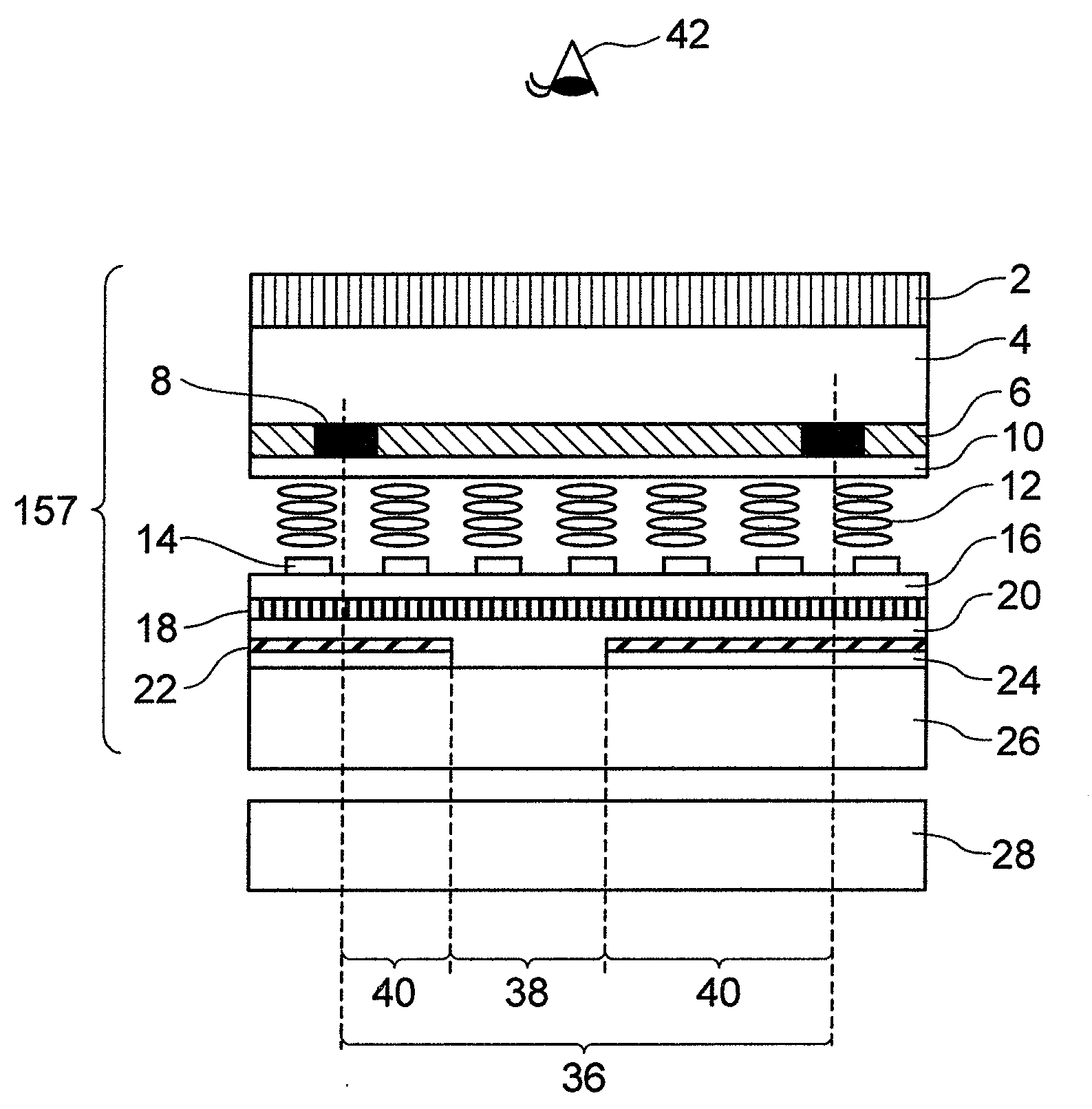
[0040]FIG. 1 shows a cross-section view of a liquid crystal display device as the first embodiment of this invention. The LCD device according to this embodiment uses a liquid crystal display element 157 of transflective type and a backlight source 28 in the form of a planar light emitting element. A liquid crystal layer 12 is disposed in the space between an upper plate 4 (second transparent plate) and a lower plate 26 (first transparent plate), both plates being disposed opposite to each other. The optical characteristic of the liquid crystal layer 12 is switched, and an upper polarizer 2 (second polarizer) and a wire grid polarizer 18 (first polarizer, hereafter referred to as WGP) disposed on that surface of the lower plate 26 which faces the liquid crystal layer 12 modulate the intensity of light so that images can be displayed.

[0041]This embodiment employs a transflective display struc...

embodiment 2

[0078]The second embodiment of this invention will now be described with reference to FIG. 12.

[0079]FIG. 12 shows a cross-section view of a liquid crystal display device as a second embodiment of this invention. This second embodiment is the same as the first embodiment described above except that a transparent common electrode 48 is provided on that surface of the metal wire layer 30 of the WGP 18 which faces the lower plate 26. Since the transparent common electrode 48 is provided in direct contact with the metal wire layer 30, the metal wire layer 30 can be maintained at the same potential throughout without separately providing electric connection among the metal wire components of the layer 30. Thus, by using transparent conductive material for the transparent common electrode 48, the sheet resistance of the transparent common electrode 48 can be reduced. The transparent common electrode 48 need not necessarily be in contact with the metal wire layer 30. Also, the transparent c...

embodiment 3

[0080]The third embodiment of this invention will be described with reference to FIGS. 13 and 14.

[0081]FIG. 13 shows a cross-section view of a liquid crystal display device as a third embodiment of this invention. This third embodiment is the same as the first embodiment described above except that the upper polarizer 2 is replaced by an upper wire grid polarizer 64 (hereafter referred to as upper WGP). The upper WGP 64 is provided on that surface of the color filter 6 which faces the liquid crystal layer 12. FIG. 14 shows a cross-section view of the upper WGP of the liquid crystal display device as a third embodiment of this invention. To absorb the TE-polarized component of the external light, light absorbing multi-film layers 62a and 62b are provided on those surfaces of the metal wire layer 30 which face the viewer's eyes 42 and the liquid crystal layer 12, respectively. The provision of the light absorbing multi-film layer 62b can prevent the degradation of contrast due to the ...


PUM


Abstract

An image is displayed by modulating TM-polarized light between the polarizer 2 and the wire grid polarizer 18 through the variation of the optical characteristic of the liquid crystal layer 12 interposed between the transparent plate 4 and the transparent plate 26. Degradation of contrast in the bright ambience is avoided by providing an absorption layer for absorbing TE-polarized light on that surface of the wire grid polarizer 18 which faces the liquid crystal layer 12.

Description

BACKGROUND OF THE INVENTION[0001]This invention relates to a wire grid polarizer and also to a liquid crystal display device of transmission type which uses such a wire grid polarizer and a liquid crystal display device of transflective type which uses such a wire grid polarizer and enjoys both transmission and reflection types of display.[0002]U.S. Pat. No. 6,348,995 discloses a reflection type image display device which provides image display by using polarized light reflected from the wire grid polarizer formed of thin closely spaced conductive elements disposed on the wavy surface of the substrate in the image display device, in order to reduce parallax and specular reflection and to improve contrast. The polarized light that passes through the wire grid polarizer is absorbed in the light absorbing layer dispose on the rear surface of the wire grid polarizer.[0003]JP-A-2005-250430 discloses a liquid crystal display (hereafter referred to also as LCD) device, intended for improve...

Claims


Application Information

Patent Timeline
IPC IPC(8): G02F1/1335G02B5/30
CPCG02B5/3058G02F2001/133565G02F2001/133548G02F1/133536G02F1/133548G02F1/133565
Inventor SUGITA, TATSUYAHIROTA, SHOICHI
Owner PANASONIC LIQUID CRYSTAL DISPLAY CO LTD
Why Eureka
Try Eureka