Low-power dram and method for driving the same

a low-power, memory-access technology, applied in the direction of information storage, static storage, digital storage, etc., can solve the problem of excessive power consumption, and achieve the effect of reducing the power consumption caused by memory access

Active Publication Date: 2008-04-24
SK HYNIX INC
View PDF5 Cites 12 Cited by
  • Summary
  • Abstract
  • Description
  • Claims
  • Application Information

AI Technical Summary

Benefits of technology

[0009]Embodiments of the present invention are directed to providing a DRAM, which...

Problems solved by technology

However, the conventional DRAM has a structural problem in that one page is enabled regardless of the size of...

Method used


Image

  • Low-power dram and method for driving the same
  • Low-power dram and method for driving the same
  • Low-power dram and method for driving the same

Examples


Embodiment Construction

[0024]Hereinafter, a low-power DRAM and a method for driving the same in accordance with the present invention will be described in detail with reference to the accompanying drawings.

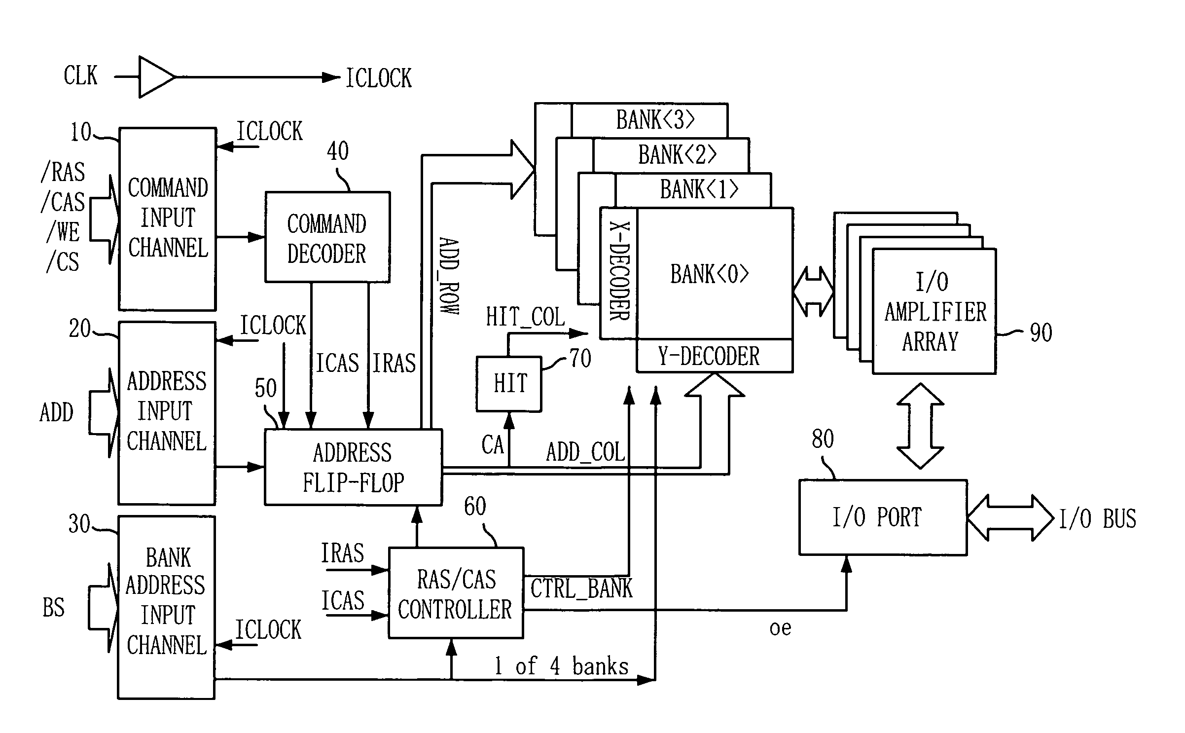
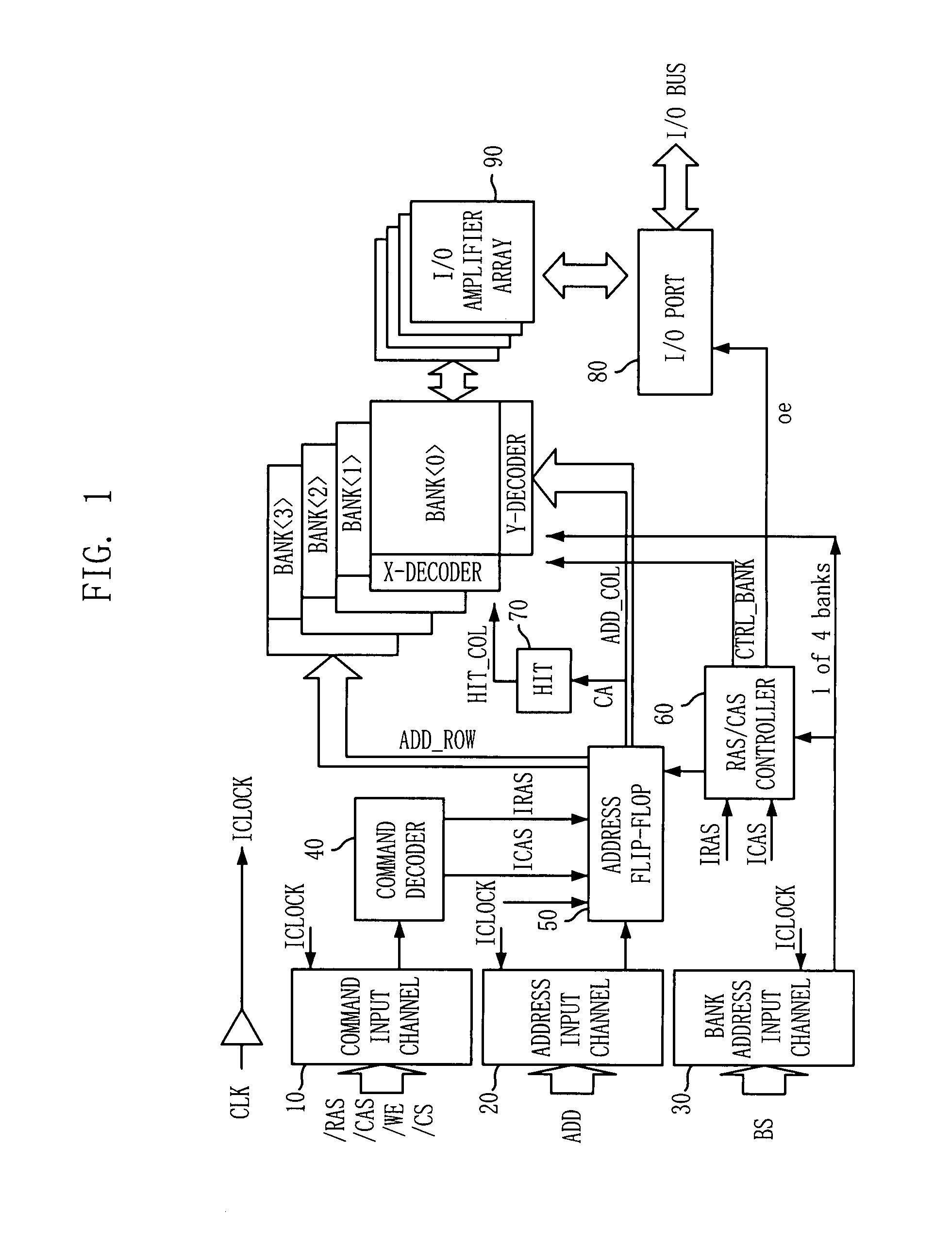
[0025]FIG. 1 is a block diagram of a DRAM in accordance with an embodiment of the present invention.

[0026]Referring to FIG. 1, the DRAM includes a command input channel 10 configured to receive commands / RAS, / CAS, / WE and / CS for an interface with the outside of the DRAM, an address input channel 20 configured to receive an address signal ADD, a bank address input channel 30 configured to receive a bank address BS, and an input / output (I / O) port 80 configured to input / output data.

[0027]Such a DRAM interface operates in synchronization with an internal clock ICLOCK produced by buffering an external clock CLK, and provides address information for enabling the DRAM, designating a location of a memory cell to be accessed, and designating data input / output location while performing data input / output cycles....


PUM


Abstract

A dynamic random access memory includes: an address latch configured to latch a row address in response to a row address strobe (RAS) signal and latch a column address in response to a column address strobe (CAS) signal; a row decoder configured to decode the row address; an enabler configured to decode a part of most significant bits (MSB) of the column address to locally enable a part of one page area corresponding to the row address; and a column decoder configured to decode the column address.

Description

CROSS-REFERENCE TO RELATED APPLICATIONS[0001]This application claims priority of Korean patent application number 10-2006-0102725, filed on Oct. 23, 2006, which is incorporated by reference in its entirety.BACKGROUND OF THE INVENTION[0002]The present subject matter relates to a semiconductor device, and more particularly, to a dynamic random access memory (DRAM) architecture.[0003]A DRAM uses a time multiplexed addressing method. A row address is latched when a row address strobe (RAS) signal is inputted, and a column address is latched when a column address strobe (CAS) signal is inputted. When the RAS signal is inputted, a predetermined memory cell array is selected and a word line driver and a sense amplifier are enabled. When the CAS signal is inputted, a read or write operation is determined. A column address to be accessed is latched and a location of data to be inputted / outputted is finally determined.[0004]Generally, before the CAS signal is inputted, a memory cell array of ...

Claims


Application Information

Patent Timeline
IPC IPC(8): G11C8/00
CPCG11C5/025G11C8/08G11C2207/2245G11C11/4087G11C11/4082G11C11/4074G11C11/408G11C11/4063
Inventor KIM, YONG-KI
Owner SK HYNIX INC
Why Eureka
Try Eureka