Semi-automatic plastic spiral binding machine

a plastic spiral binding machine and semi-automatic technology, applied in the field of book binding, can solve the problem that the exact tool for the particular thickness cannot be used to form the sheets properly, and achieve the effect of reducing the cling

Inactive Publication Date: 2008-04-24
SPIEL ASSOCS
View PDF3 Cites 3 Cited by
  • Summary
  • Abstract
  • Description
  • Claims
  • Application Information

AI Technical Summary

Benefits of technology

[0021]To help prevent pages from clinging to each other and to help them rest on the convex rest during book forming, a vibrator vibrates the page forming carriage by transmitting vibration via the curved side brackets. A pneumatic vibrator of the circulating ball variety is used. This operates on a normal compressed air or “shop air” supply, only during the book forming process.
[0022]An artifact of this type of vibrator is that its exhaust is a pulsating stream of compressed air. In this invention, an aerat

Problems solved by technology

Most often, the exact tool for the particular thi

Method used


Image

  • Semi-automatic plastic spiral binding machine
  • Semi-automatic plastic spiral binding machine
  • Semi-automatic plastic spiral binding machine

Examples


Embodiment Construction

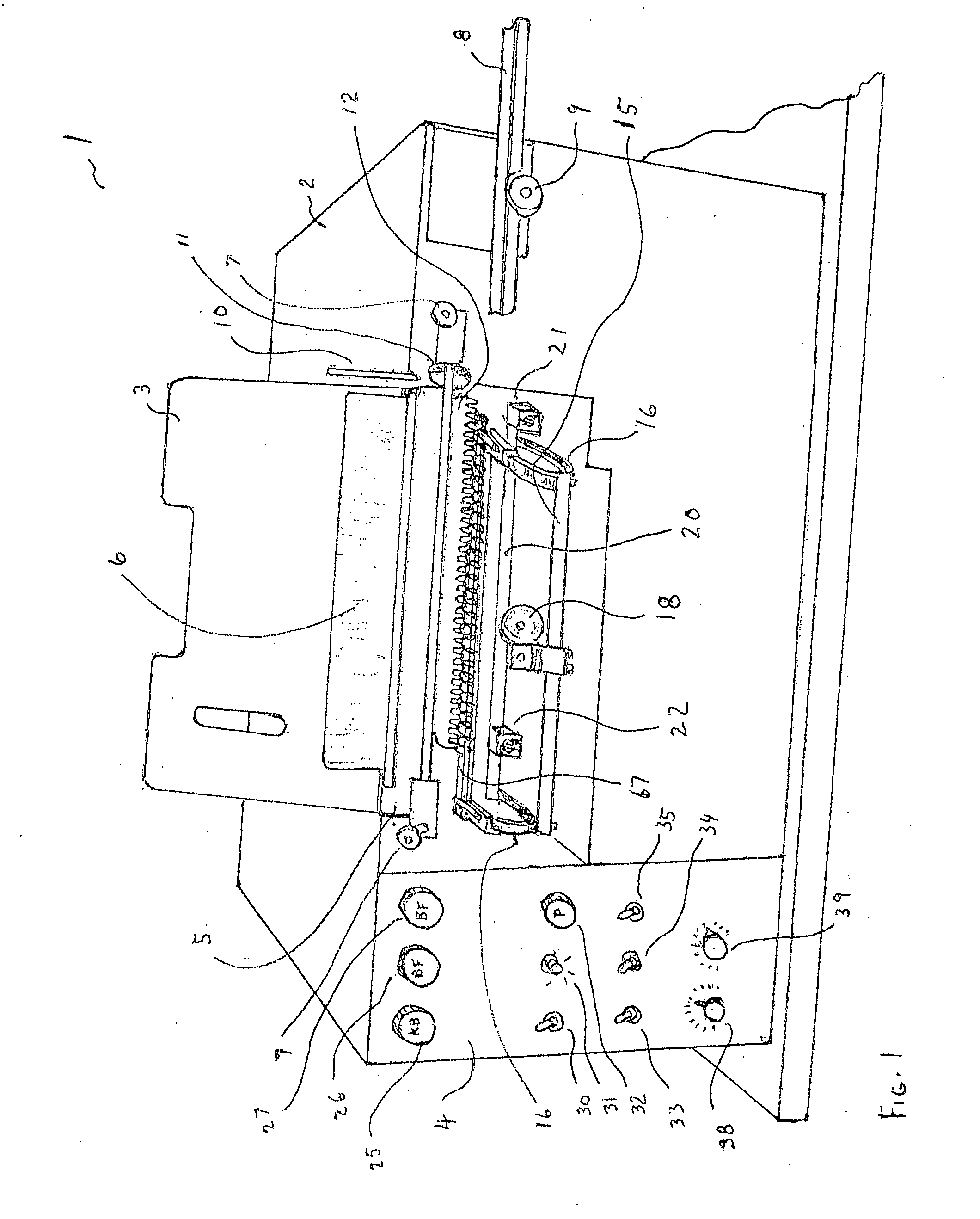
[0041]FIG. 1 shows binding machine 1 of this invention prior to the introduction of the book pages. Housing 2 encloses the pneumatic and electrical components of this table-top binding machine. Operating panel 4 houses the operator controls. Circular arc brackets 16 connect book forming carriage bar 67 to vibrator bar 15 (with vibrator 18) to cutter bar 20 (with cutter / crimpers 22 and 21) permitting the book forming carriage bar 67 to be raised into position as shown or alternatively the cutter bar 20 to be placed into position at that phase of the operation, as shown in FIG. 5.

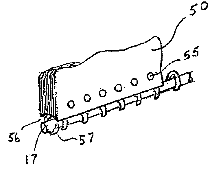
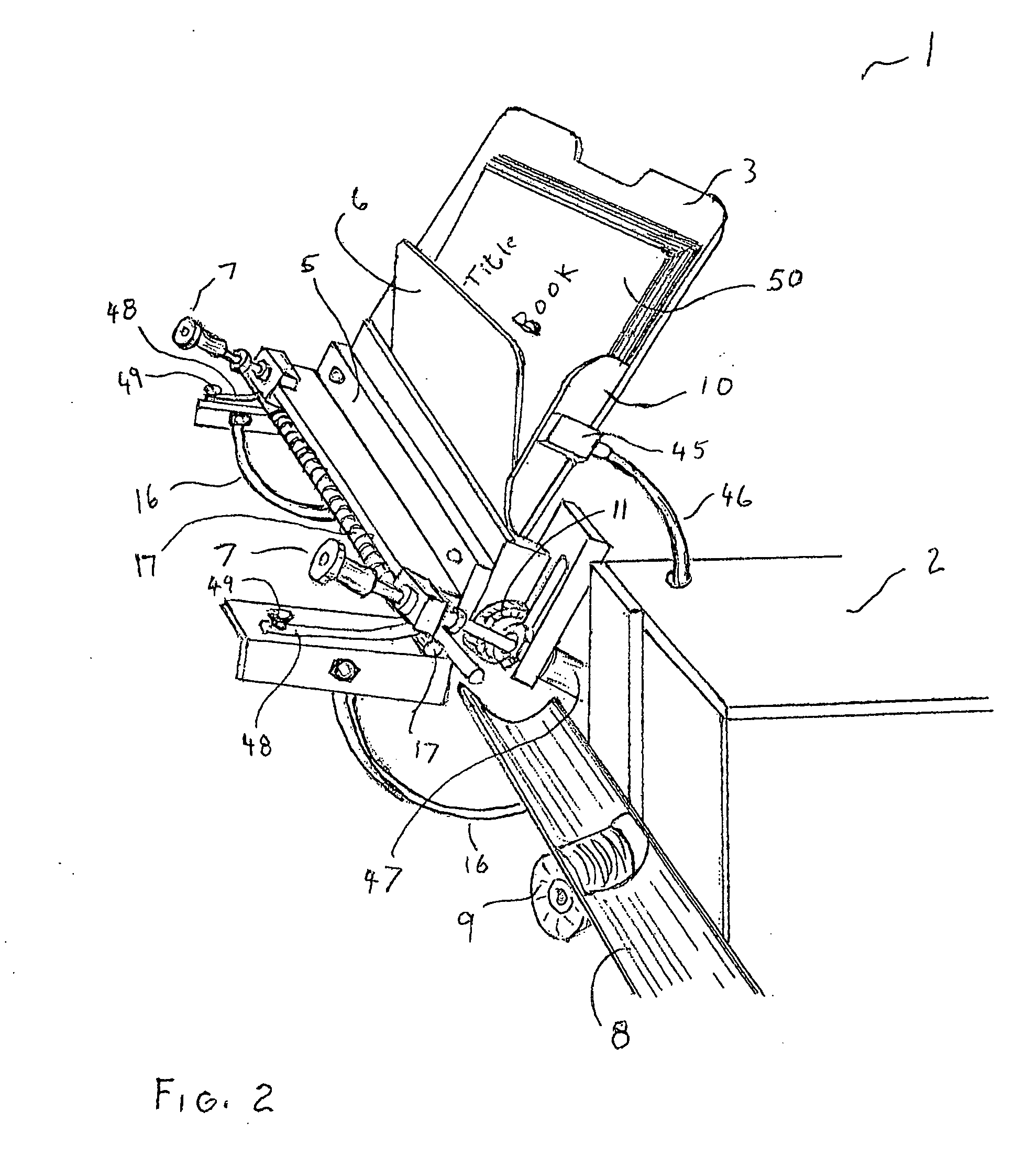
[0042]As shown in FIGS. 1 and 2, back book support 3 is angled backwards while page guide 6 is angled forward. Angled stop 10 sets the pitch angle to match the binding spiral. Comb guide 12 guides a binding spiral during insertion. A page holder, such as book clamp 5, with gap adjusters 7 holds the book pages together after forming. Spiral conveyor or trough 8 receives the binding spiral which is conveyed int...


PUM


Abstract

A book binding machine has a page-forming mode and a spiral-binding mode, where a curved inexpensive piece of binding spiral coil or a convex member form a collection of pages being bound into a concavity on the spine of the pages to be bound with a proper pitch angle to accept insertion of a plastic spiral binding coil. An optional pivoting page-forming carriage and an optional pivoting cutter/crimper are respectively movable between engaged and disengaged positions. The book forming bar is optionally moved out of the way in an intermediate position while the spiral is spun into the perforations. Then the brackets place the cutter bar in position. Pulsed air is preferably used to operate the vibrator and the exhaust pulsed air is fed to a page aerating manifold to keep pages from clinging to each other prior to the sheets being clamped before insertion of the plastic spiral coil.

Description

FIELD OF THE INVENTION[0001]The present invention relates to book binding with a compact machine having a page-forming mode and a spiral-insertion and cutting with bending mode, where a curved foundation forms a collection of pages being bound into a concave edge, and an angled side guide sets a proper pitch angle to accept insertion of a plastic spiral binding coil.BACKGROUND OF THE INVENTION[0002]Existing book binding coil insertion machines insert plastic spiral coil into a collection of pages being bound. Previously, such book binding machines have been large, and have several sequential functions to accomplish forming up pages, inserting plastic coils and cutting and crimping the coils. While forming up the pages, the proper tool must be selected from a set so as to match the variety of book thickness being bound. Most often, the exact tool for the particular thickness is unavailable to form the sheets properly.[0003]Each plastic spiral gets inserted through the holes in a stac...

Claims


Application Information

Patent Timeline
IPC IPC(8): B42B4/00B42B9/00
CPCB42F5/04B42B5/123
Inventor SPIEL, NORTON
Owner SPIEL ASSOCS
Why Eureka
Try Eureka