Vertical axis wind turbine with articulating rotor

Inactive Publication Date: 2008-04-24
BOATNER BRUCE E
View PDF22 Cites 46 Cited by
  • Summary
  • Abstract
  • Description
  • Claims
  • Application Information

AI Technical Summary

Benefits of technology

[0019] A wind engine constructed according to the fully articulating rotor aspect of the invention also includes a support structure and a rotor mounted on the support structure for rotation about a vertically extending rotational axis. However, the rotor is mounted in a manner enabling full 360-degree articulation for rotor tilting purposes. In other words, the rotor includes and is mounted with a rotor hub assembly that provides a 360-swiveling action

Problems solved by technology

The second, self-orienting-pitch VAWTs, includes those using reactive elements that orient themselves relative to the wind without a separate control means (less-than-ideal angle-of-attack due to the delay inherent in repositioning the airfoil reactive elements in response to the

Method used


Image

  • Vertical axis wind turbine with articulating rotor
  • Vertical axis wind turbine with articulating rotor
  • Vertical axis wind turbine with articulating rotor

Examples


Embodiment Construction

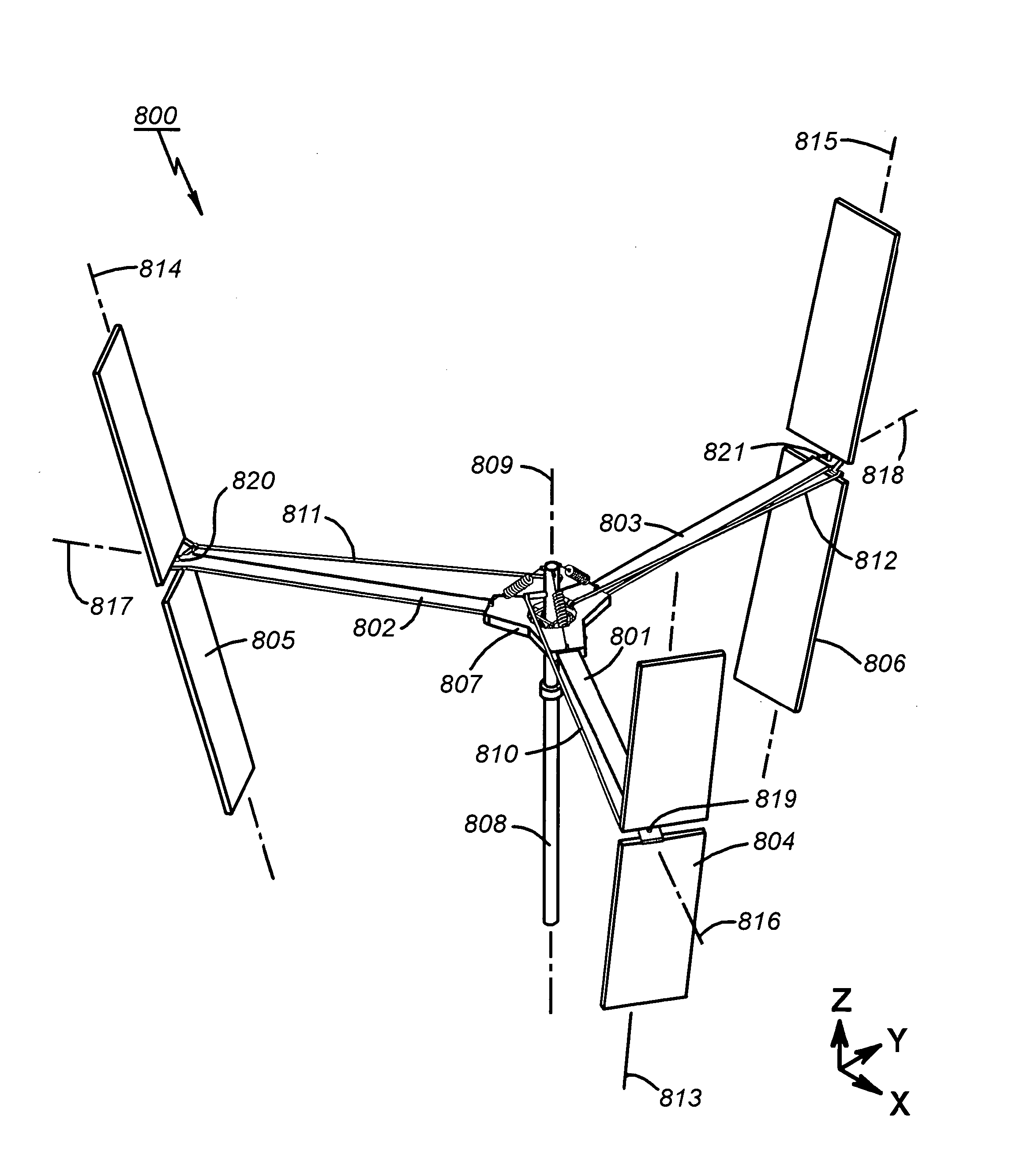
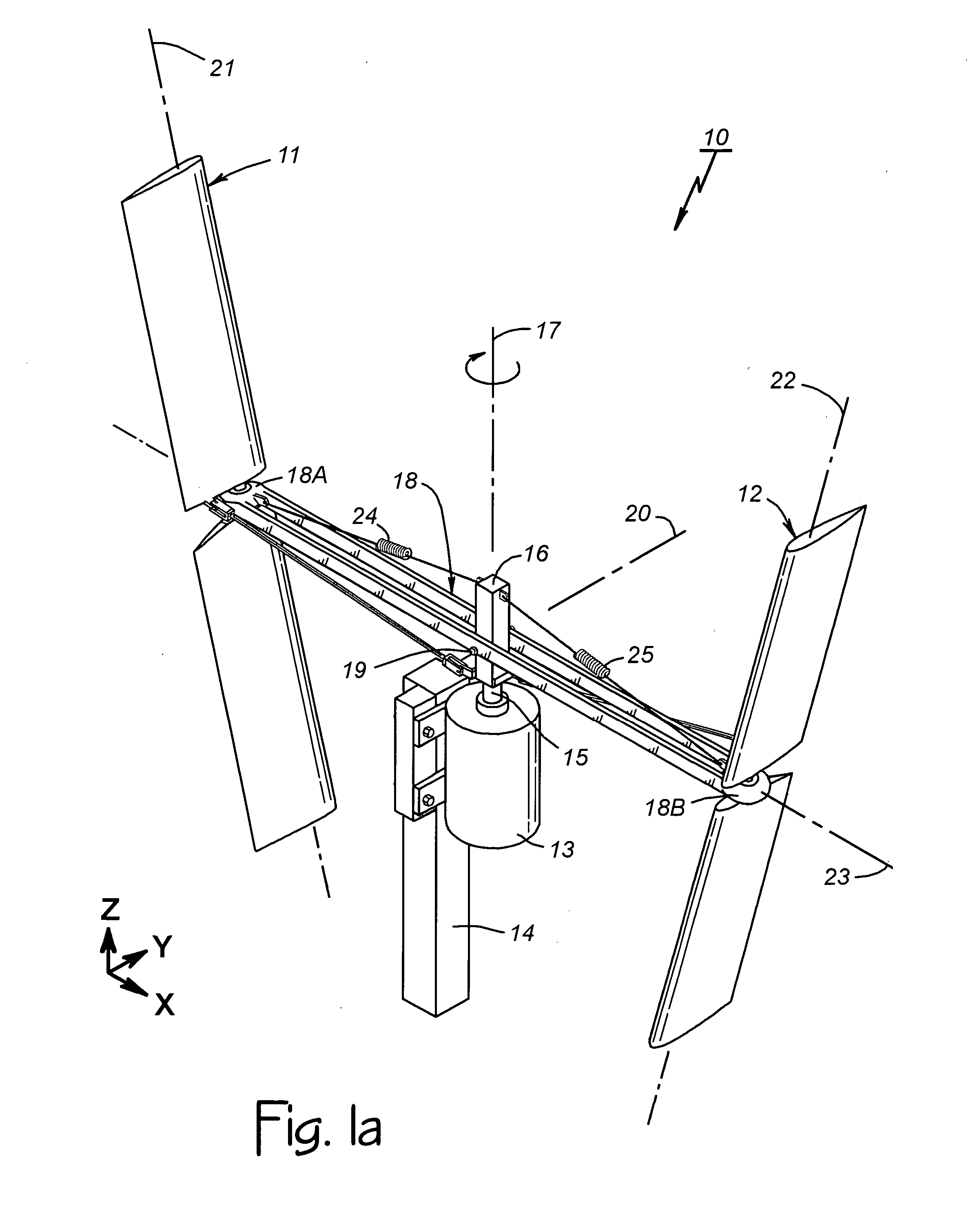
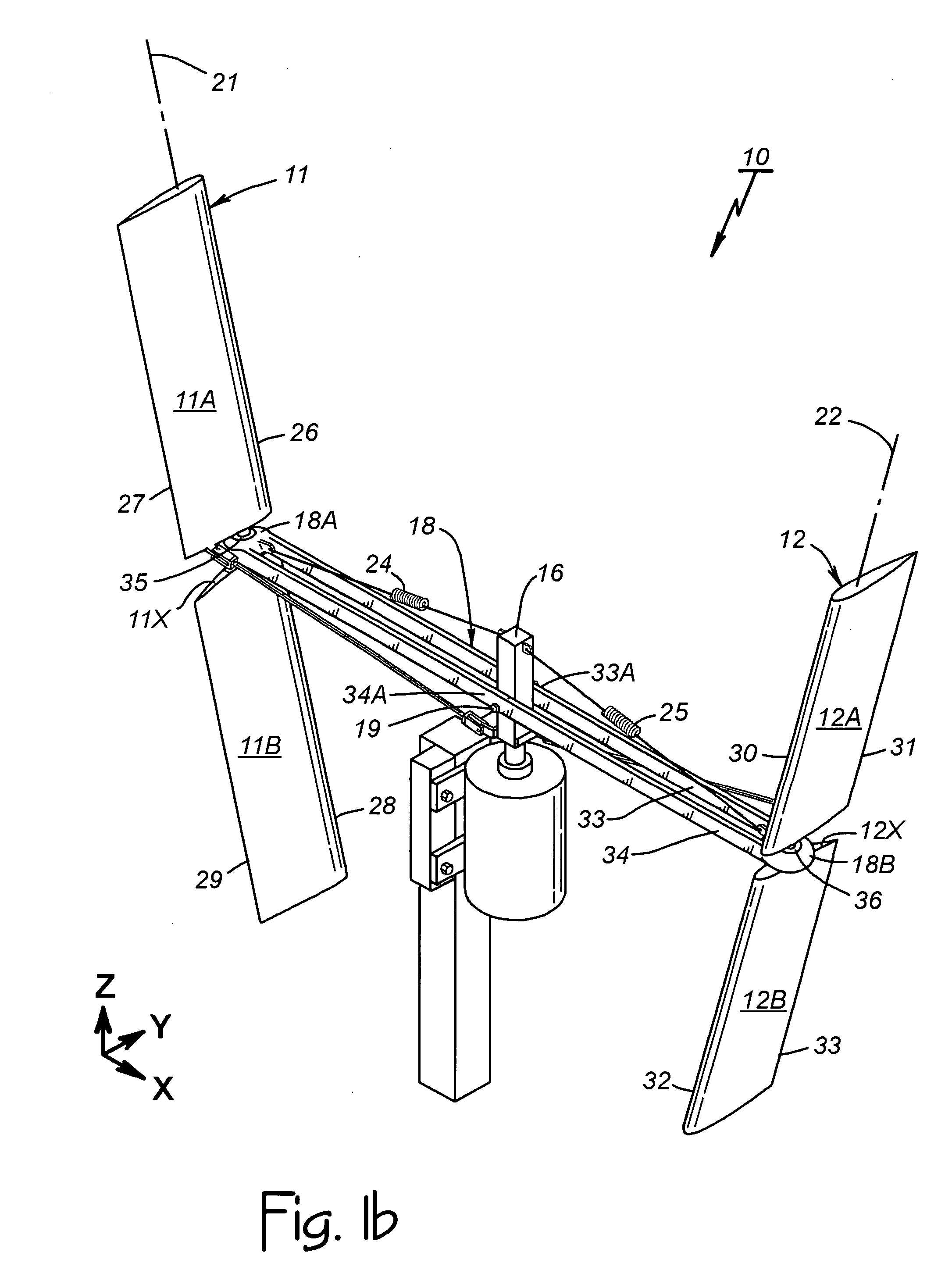
[0042] First Partially Articulating Embodiment. FIG. 1a of the drawings is a perspective view of a vertical axis wind turbine (i.e., a wind engine) constructed according to the invention. It is identified as a VAWT 10 and it operates in lift mode with mechanically-controlled-pitch and fixed geometry. Generally, the VAWT 10 includes first and second airfoils 11 and 12 that respond to oncoming wind to power a load 13 (e.g., a gear box coupled to a generator that produces electrical power). The load 13 is part of a support structure 14 that includes the load 13, a drive shaft 15 connected to the load 13, and a vertically extending mast 16 connected to the drive shaft 15 for rotation with the drive as a vertically extending support structure extension. The airfoils 11 and 12 cause the mast 16, and thereby the drive shaft 15, to rotate about a vertically extending axis of rotation 17 in response to oncoming wind, doing so with a teetering rotor 18.

[0043] The airfoils 11 and 12 are cante...


PUM


Abstract

A VAWT wind engine includes a support structure, an articulating rotor mounted on the support structure for rotation about a vertically extending axis, and at least one airfoil on the rotor for rotor-powering purposes. The articulating rotor is mounted in a manner enabling tilting movement of the rotor during rotation so that the airfoil produces rotor rotation and rotor tilt as the airfoil orbits the rotational axis. At least one mechanical linkage is included to actively vary airfoil pitch according to rotor tilt. The partially articulating rotor of a teetering-rotor embodiment seesaws up and down about a horizontally extending pivotal axis. The fully articulating rotor of another embodiment supports three airfoils as it tilts in any direction by virtue of a gimbal or other rotor hub assembly providing a 360-degree swiveling action, while furling hinges help protect the airfoils against damaging winds during wind engine shutdown.

Description

CROSS REFERENCE TO RELATED APPLICATION [0001] This application is a continuation in part of copending U.S. patent application Ser. No. 11 / 501,088 filed on Aug. 7, 2006.BACKGROUND OF THE INVENTION [0002] 1. Technical Field [0003] This invention relates generally to wind turbines and the like, and more particularly to a vertical axis wind turbine that utilizes the kinetic energy of moving air to provide rotational energy useable for generating electric power and / or other useful purposes. [0004] 2. Description of Related Art [0005] The goal of any wind turbine is to extract power from the wind. In 1919 Albert Betz theorized that the efficiency limit for wind energy conversion is 59.3% and emphasized that since energy is derived from the movement of air molecules, one should avoid slowing the incoming air mass by more than about one-third. Based on the work of Betz, wind turbine technology has evolved toward the use of a minimum number of airfoils traveling at a maximum practical speed,...

Claims


Application Information

Patent Timeline
IPC IPC(8): F03D7/06
CPCF03D3/068Y02E10/74F05B2260/70F03D7/06Y10S415/907
Inventor BOATNER, BRUCE E.
Owner BOATNER BRUCE E
Why Eureka
Try Eureka