Articulating laparoscopic device and method for delivery of medical fluid

a laparoscopic device and medical fluid technology, applied in the field of laparoscopic devices, can solve the problems of inability to reach rigid laparoscopic delivery devices, difficult to maneuver the applicationator from the opposite proximal end of the tubular member, and the structure and operation of variable curved catheters are rather complicated, so as to achieve the effect of small size, simple operation and cost-effectiveness

Inactive Publication Date: 2008-04-24
ETHICON INC
View PDF8 Cites 34 Cited by
  • Summary
  • Abstract
  • Description
  • Claims
  • Application Information

AI Technical Summary

Benefits of technology

[0021]It is yet another object of the present invention to provide a method and apparatus for laparoscopically delivering trapped medical fluid in an internal lumen of a fluid delivery device, which apparatus does not affect the tactile feel of the fluid delivery device, thus enabling the physician to precisely deliver a medical fluid to the patient at a...

Problems solved by technology

Because of their rigidity, these applicators are difficult to maneuver from the opposite proximal end of the tubular member for precisely directing the adhesive or sealant to the targeted area, without dripping the adhesive or sealant on non-targeted tissue.
Oftentimes, laparoscopic delivery of such medical fluids requires the ability to reach behind anatomical structures (e.g., organs, large vessels and the like) to the targeted site, which rigid laparoscopic delivery devices are incapable of reaching.
The disclosed Karmarkar et al. variable curved catheter is a rather complicated device structurally and operationally.
It is complex and labor intensive to manufacture, and requires a two-handed operation.
It, too, is complex structurally, and labor-intensive and costly to manufacture.
The DeLaRama et al. multi-slotted miniscope is another example of a structurally complicated laparoscopic device which is also costly to manufactu...

Method used


Image

  • Articulating laparoscopic device and method for delivery of medical fluid
  • Articulating laparoscopic device and method for delivery of medical fluid
  • Articulating laparoscopic device and method for delivery of medical fluid

Examples


second embodiment

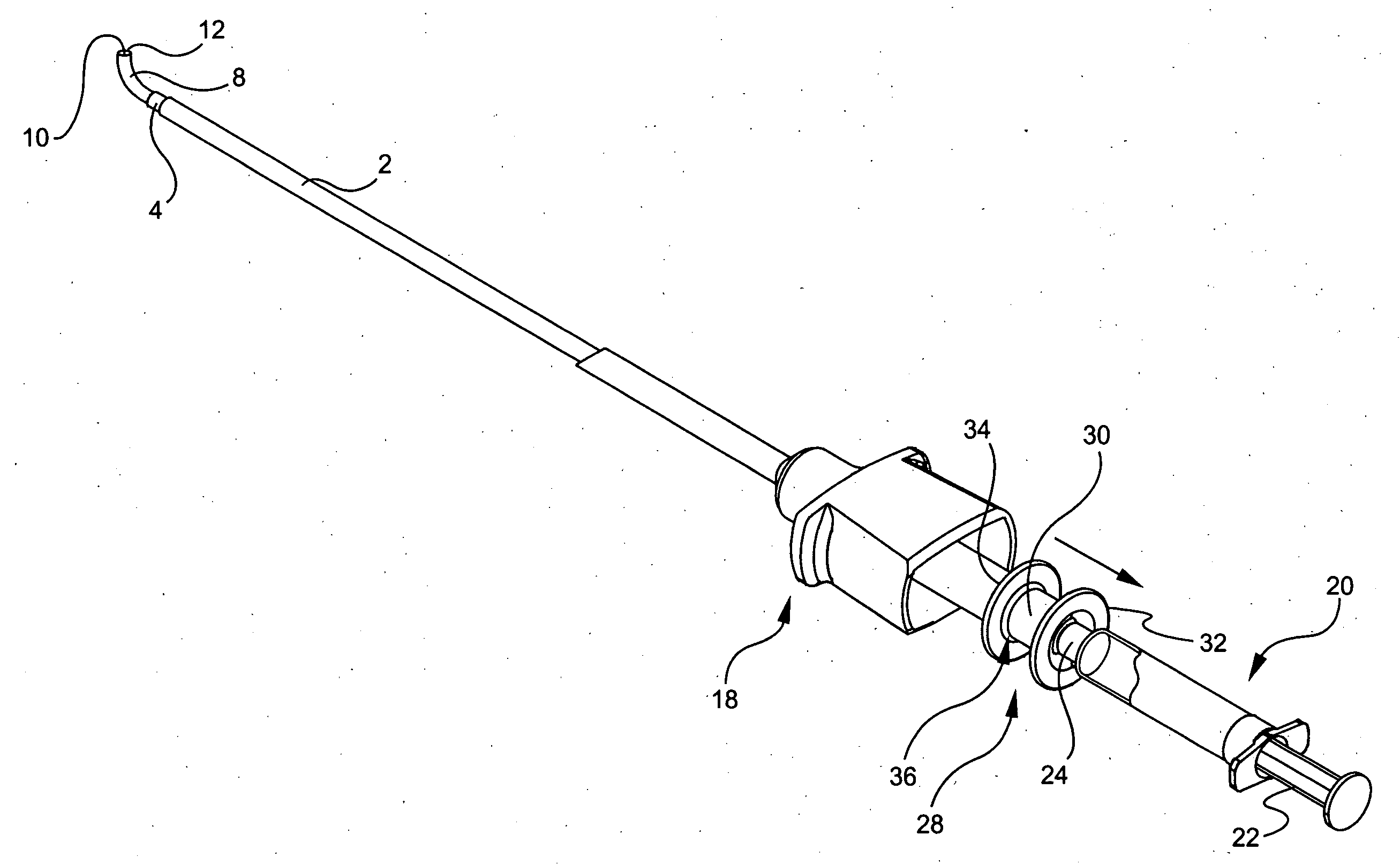
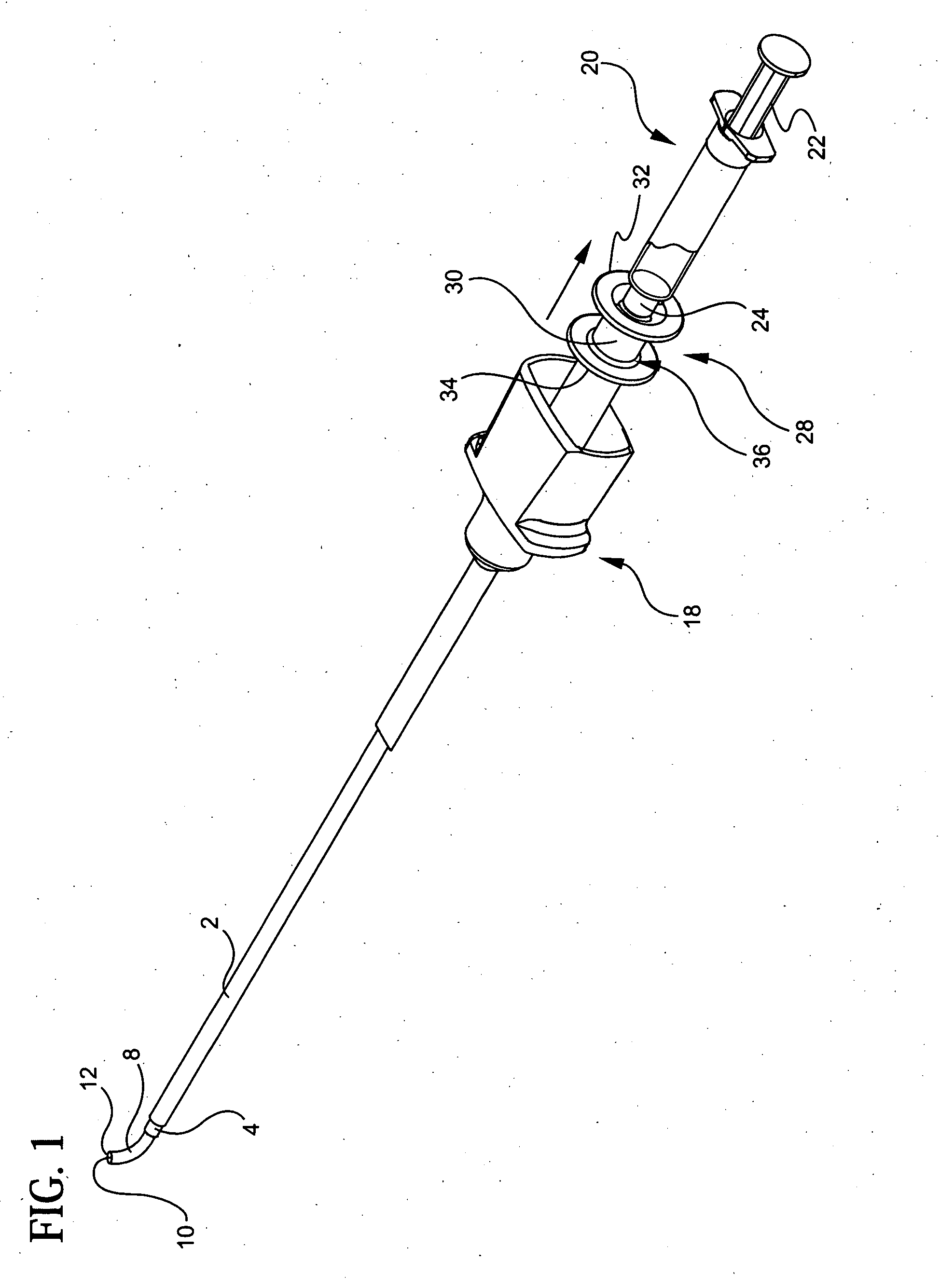
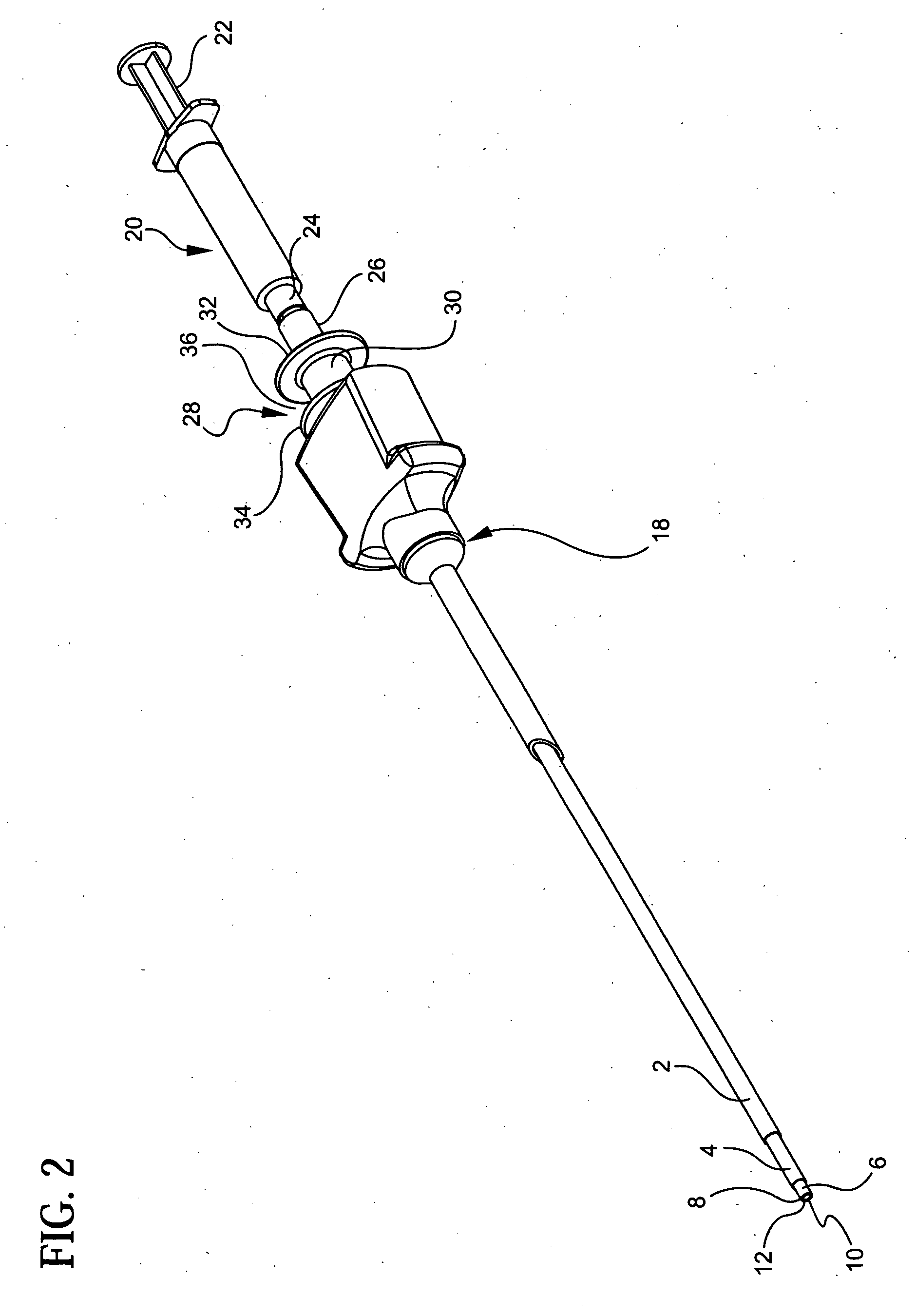
[0102]In the present invention, the articulating laparoscopic medical fluid delivery device of the present invention may include an actuator constituted as a handle with a trigger operatively linked to the inner tubular member 4 to move the inner tubular member with respect to the flexible catheter 6 and the outer tubular member 2. As shown in FIGS. 16-20 of the drawings, with this particular embodiment, the laparoscopic fluid delivery device generally includes a handle 52 for grasping by the surgeon, the top of which is formed with a barrel 54 for receiving and holding in place the syringe 20 containing the medical fluid to be delivered to the patient. More specifically, the handle 52 includes a housing 56 defining a handle portion 58 for grasping by the surgeon, and an upper portion 60 defining a barrel 54 for receiving therein the syringe 20. The barrel 54 is arranged on the handle 52 such that the syringe tip, with its luer lock fitting 24, is co-axially situated with the lumen ...

third embodiment

[0109]An alternative version of the laparoscopic medical fluid delivery device of the present invention is illustrated by FIGS. 28-35. Here, the device allows the articulating distal tip 8 of the catheter 6 to rotate three hundred, sixty degrees (360°) so that the surgeon can even more precisely direct medical fluid to the targeted tissue site within the patient. One form of the structure which allows the catheter tip 8 to rotate is illustrated by FIGS. 28-35 of the drawings and will be described below, although it is envisioned to be within the scope of the present invention to provide other structure that allows the catheter 6 and / or the articulating catheter tip 8 to rotate.

[0110]More specifically, the luer lock fitting or connector 102 which is mounted to the proximal end 14 of the catheter, or other syringe adaptor that mates with the syringe, is situated within the cavity 96 of the handle housing 76 and is free to rotate therein. The sidewall of the fitting or connector 102 in...

fourth embodiment

[0121]the laparoscopic medical fluid delivery device of the present invention is shown in FIGS. 41-47. In this embodiment, the inner tubular member 4 is retracted or advanced on the fluid delivery catheter 6 by rotating a nose piece 144. With this embodiment, the outer tubular member 2, moveable inner tubular member 4 and catheter 6, arranged as described previously in the other embodiments, are mounted to a handle 146, forming part of the actuator of the laparoscopic device, having a handle portion 148 which is graspable by the surgeon. The front end of the handle 146 is formed with a nose piece 144 that is rotatably mounted thereon. The nose piece 144 has a central bore 150 formed axially therethrough. This bore 150 is threaded. The outer tubular member 2 is affixed to the front of the nose piece 144 and rotates with it. The catheter 6 passes through the nose piece bore 150, and has a proximal end which is attached to a luer lock fitting or connector 152, which fitting or connecto...


PUM


Abstract

A laparoscopic medical fluid delivery device includes a catheter having an articulating tip formed with shape memory properties and thus having a pre-shaped curvature. A tubular member is reciprocatingly slidable axially on the catheter to selectively cover and uncover portions of the articulating tip to thereby selectively vary the degree of curvature of the articulating tip. An actuator operatively linked to the tubular member selectively moves the tubular member reciprocatingly on the catheter. The pre-shaped articulating tip of the catheter is constrained by the tubular member from articulating to the pre-shaped curvature when the tubular member covers the articulating tip, and bends to a selected degree of curvature when the articulating tip is at least partially uncovered by the tubular member.

Description

BACKGROUND OF THE INVENTION[0001]1. Field of the Invention[0002]The present invention generally relates to laparoscopic devices, and more particularly relates to bendable laparoscopic applicators of medical fluids or agents, such as sealants, adhesives, flowable haemostatic agents and antibiotics. This invention also particularly relates to methods for delivering such medical fluids to a patient.[0003]2. Description of the Prior Art[0004]Certain conventional laparoscopic adhesive or sealant applicators include a straight and rigid elongated tubular member having an internal lumen communicating with a distal opening through which the adhesive or sealant passes. Because of their rigidity, these applicators are difficult to maneuver from the opposite proximal end of the tubular member for precisely directing the adhesive or sealant to the targeted area, without dripping the adhesive or sealant on non-targeted tissue. Oftentimes, laparoscopic delivery of such medical fluids requires the...

Claims


Application Information

Patent Timeline
IPC IPC(8): A61M25/01
CPCA61B17/00491A61M5/31511A61M25/0068A61M25/0074A61M2025/0076A61M25/0152A61M25/0662A61M2005/31516A61M2025/0004A61M25/008
Inventor FEINBERG, MARCLIBERATORE, JESSICAKOCHARIAN, RICHARDZABOROWSKI, BRUCE E.
Owner ETHICON INC
Why Eureka
Try Eureka