Catheter With Adjustable Stiffness

a catheter and adjustable technology, applied in the direction of catheters, etc., can solve the problems of increasing the possibility of complications, stiff catheters are difficult to navigate through tortuous vessels, and the catheter requires a certain degree of stiffness

Inactive Publication Date: 2008-04-24
SACHAR RAVISH +1
View PDF12 Cites 39 Cited by
  • Summary
  • Abstract
  • Description
  • Claims
  • Application Information

AI Technical Summary

Benefits of technology

[0012] Stated generally, the present invention relates to a catheter having a portion of its shaft adjacent the proximal end being of adjustable stiffness. A portion of the catheter shaft adjacent its proximal end has an outer catheter wall and an inner catheter wall defining a space therebetween. An electrode is disposed with

Problems solved by technology

One fundamental problem is that, in order to deliver stents to the appropriate location in the carotid artery or in the intracranial circulation, the catheter requires a certain degree of stiffness.
However, stiff catheters are difficult to navigate through the tortuous vessels characteristic of the carotid arteries and intracranial vessels.
Thus, in order to position a stiff catheter for stent delivery, multiple guide wires and catheters must be interchanged inside the patient before a catheter of appropriate stiffness is in place, adding to the possibility of complications.
For example, treatment of superficial femoral artery stenoses often requires a contralateral approach with multiple catheter exchanges, which increases procedural time and risk, and further increases the radiation exposure to the operator.
Without a catheter, the stent would cause tremendous damage to blood vessel walls as it scraped them en route to the site of a stenosis.
There are two major problems wi

Method used


Image

  • Catheter With Adjustable Stiffness
  • Catheter With Adjustable Stiffness
  • Catheter With Adjustable Stiffness

Examples


Embodiment Construction

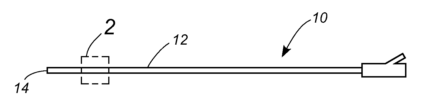
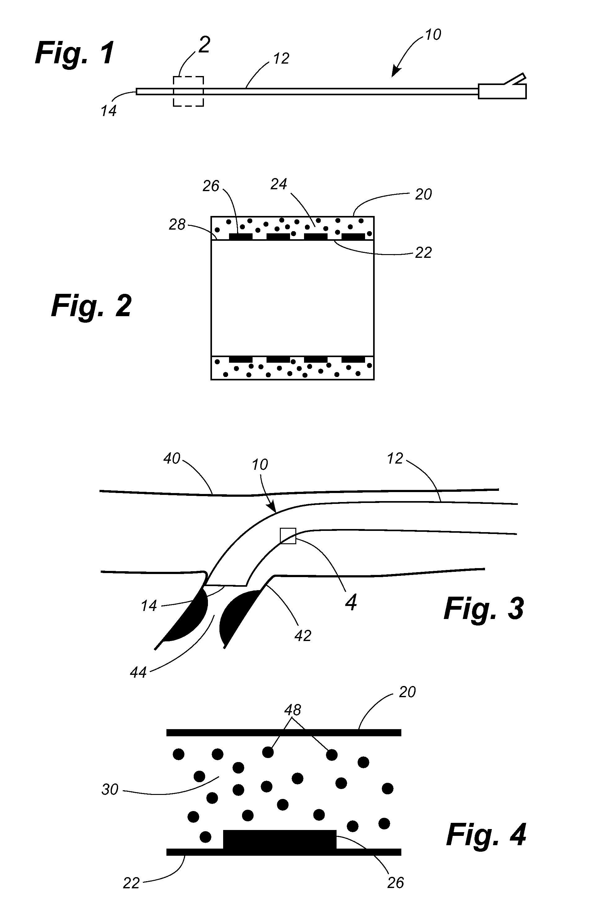
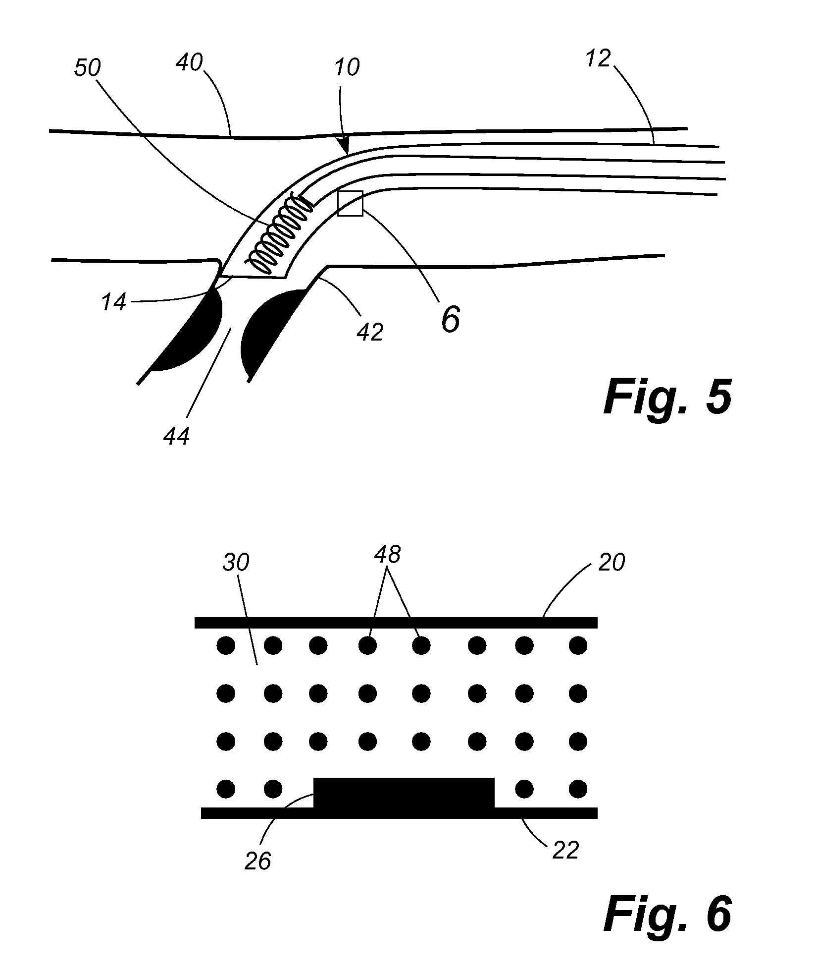
[0022] Referring now to the drawings, in which like numerals indicate like elements throughout the several views, FIG. 1 shows a catheter 10 having a shaft 12 with a proximal end 14. As shown in FIG. 2, a portion 16 of the catheter shaft 12 adjacent the proximal end 14 has an outer wall 20 and an inner wall 22. An annular space 24 is formed between the inner and outer walls 20, 22. In the disclosed embodiment the length of the catheter shaft comprising the concentric tubes is approximately six to eight inches in length. A plurality of electrode sections 26 are formed on the outer surface 28 of the inner wall 22. A magnetorheological (MR) fluid 30 fills the annular space 24 between the inner and outer walls 20, 22.

[0023] The catheter 10 is normally soft and pliable. However, when a magnetic field is applied to the MR fluid 30 in the portion of the shaft 12 adjacent the proximal end 14 of the catheter 10, that portion of the shaft stiffens, as is characteristic of MR fluids. FIG. 3 i...


PUM


Abstract

A catheter has a section of the catheter shaft adjacent its proximal end in which an outer catheter wall and an inner catheter wall define a space therebetween. An electrode is disposed within the space defined between the inner and outer catheter walls. A magnetorheological fluid fills the space between the inner and outer catheter walls. When an electric current is passed through the electrode, the magnetorheological fluid stiffens, causing the section of the catheter shaft adjacent the proximal end to stiffen.

Description

TECHNICAL FIELD [0001] The present invention relates generally to catheters and relates more specifically to a catheter having a shaft with adjustable stiffness. BACKGROUND OF THE INVENTION [0002] Stents are an increasingly popular treatment modality for stenosed blood vessels within the body via minimally invasive techniques. Stenting procedures for cardiac vessels are well established. However, procedures for percutaneously treating carotid, and especially intracranial, stenoses are still evolving. There are several unmet needs for the treatment of carotid and intracranial atherosclerosis. One fundamental problem is that, in order to deliver stents to the appropriate location in the carotid artery or in the intracranial circulation, the catheter requires a certain degree of stiffness. However, stiff catheters are difficult to navigate through the tortuous vessels characteristic of the carotid arteries and intracranial vessels. Thus, in order to position a stiff catheter for stent ...

Claims


Application Information

Patent Timeline
IPC IPC(8): A61M25/00
CPCA61M2025/0063A61M25/0054
Inventor SACHAR, RAVISHWALKER, GLENN M.
Owner SACHAR RAVISH
Why Eureka
Try Eureka