Eureka AIR delivers breakthrough ideas for toughest innovation challenges, trusted by R&D personnel around the world.

Morphological structures for polymeric drug delivery devices

Inactive Publication Date: 2008-04-24
CORDIS CORP
View PDF9 Cites 76 Cited by
  • Summary
  • Abstract
  • Description
  • Claims
  • Application Information

AI Technical Summary

Benefits of technology

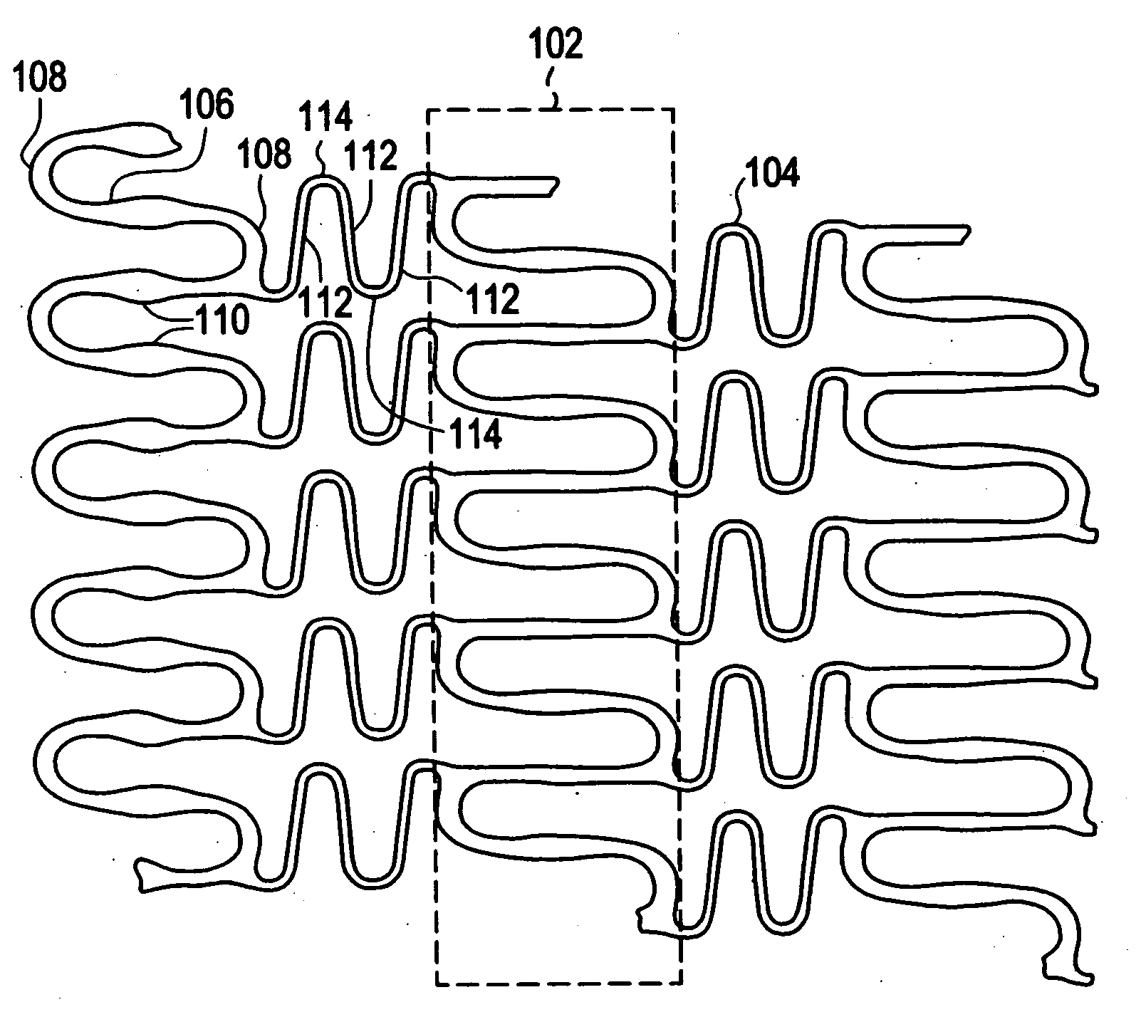
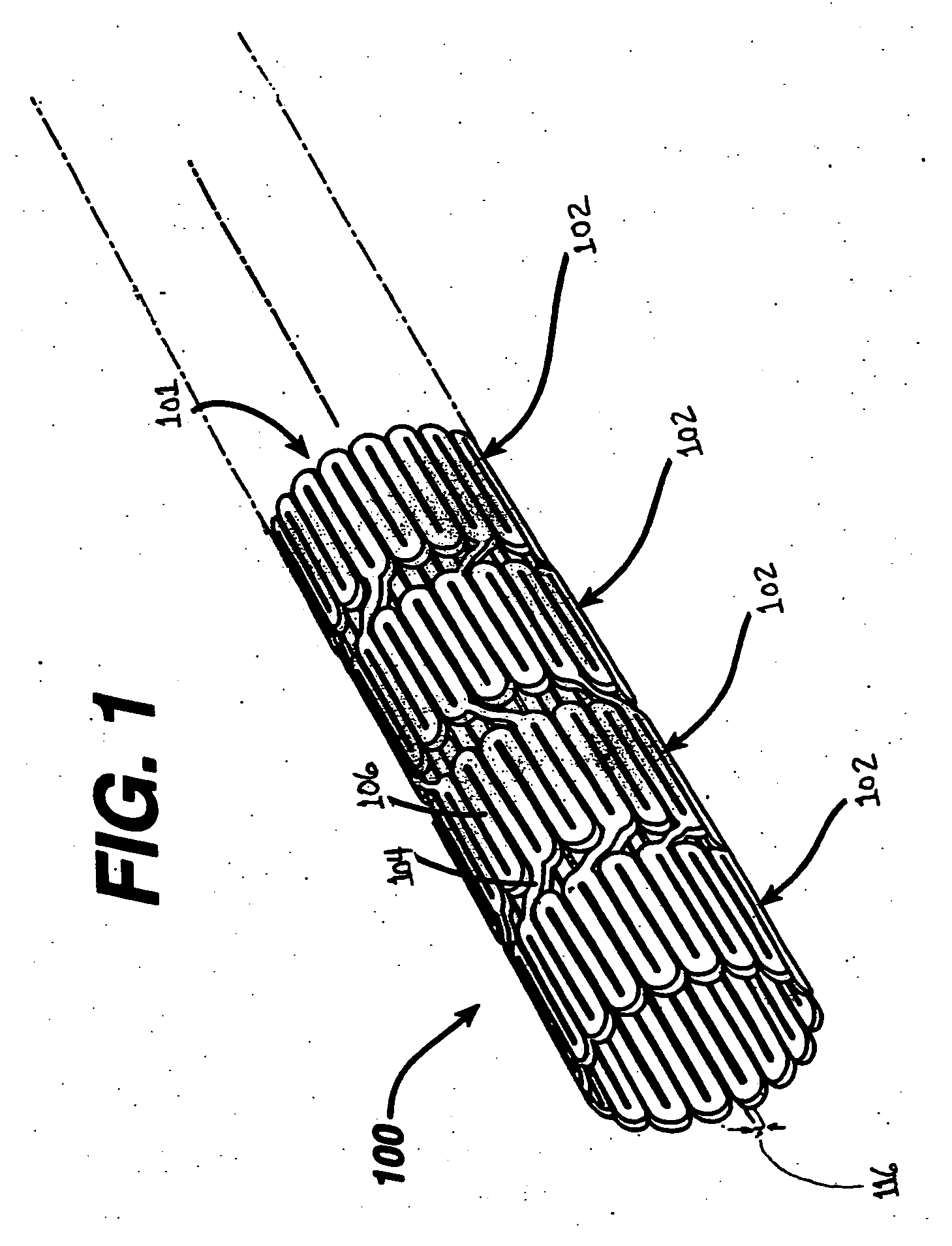
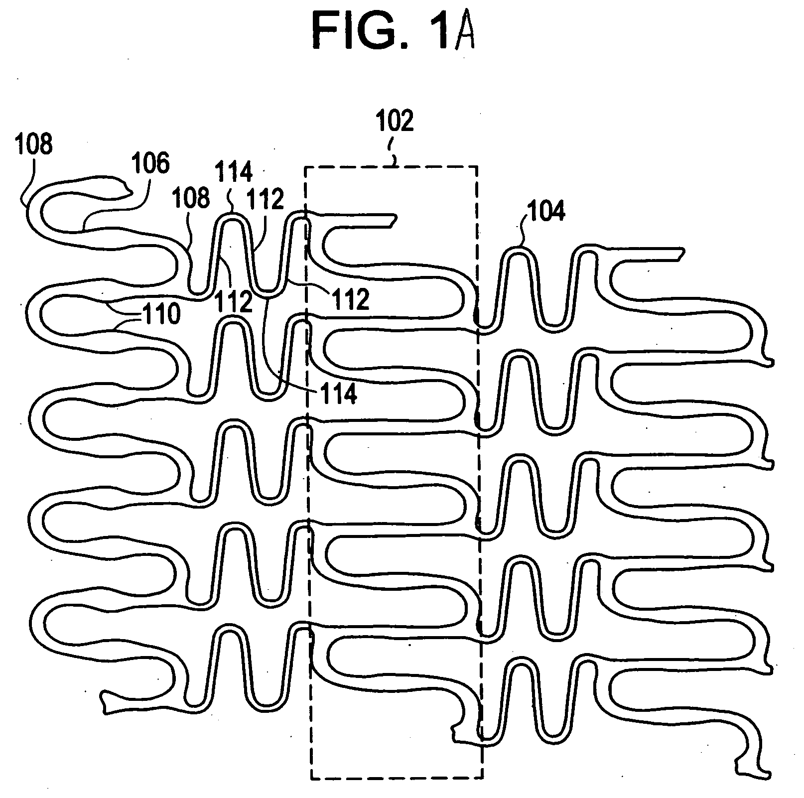
[0007]The present invention generally comprises an intraluminal device constructed from a unique polymeric composition having properties that allow the implantable medical device to enhance performance characteristics such as high radial stiffness, minimized recoil values, and improved flexibility. More particularly, the molecular structure of the composition facilitates the design of medical devices with a wide range of geometries that are adaptable to various loading conditions. The composition and the medical devices constructed may be utilized for any number of medical applications, including vessel patency devices, such as vascular stents, biliary stents, ureter stents, vessel occlusion devices such as atrial septal and ventricular septal occluders, patent foramen ovale occluders and orthopedic devices such as fixation devices.
[0008]Forming a medical device, such as an implantable or intraluminal medical device, from bioabsorbable polymers must be accomplished in such a manner as to insure that the device maintains patency when implanted into a vessel or other conduit within a body. For example, a polymeric stent is typically implanted into a vessel by expansion with a balloon or some other expandable means. It is crucial to ensure that the stent impinges upon the inner wall of the vessel. After expansion, however, the polymer stent will experience shrinkage or recoil that causes it to lose apposition. Thus, it is desirable to minimize recoil. The morphology or arrangement of the polymeric structure is optimized in the present invention to reduce recoil.
[0010]The present invention reduces the crystallinity of the polymer composition while preserving the crystallinity and efficacy of the therapeutic drug by creating a generally amorphous polymeric structure. Amorphous polymeric structures experience a higher level of viscous deformation at all temperatures. This type of deformation tends to be permanent in nature leading to lower recoil values of the device constructed therefrom. The present invention obtains the optimal amorphous structure by heating the polymer to at least the melting transition temperature followed by rapid quenching to prevent any recrystallization of the polymer. The polymer selected typically has a melt transition temperature below the melt transition temperature for the drug mixed therewith. Thus, the drug maintains its crystallinity and experiences minimal degradation during this process.
[0011]The devices of the present invention may also be formed from blends of polymeric materials, blends of polymeric materials and plasticizers, blends of polymeric materials and therapeutic agents, blends of polymeric materials and radiopaque agents, blends of polymeric materials with both therapeutic and radiopaque agents, blends of polymeric materials with plasticizers and therapeutic agents, blends of polymeric materials with plasticizers and radiopaque agents, blends of polymeric materials with plasticizers, therapeutic agents and radiopaque agents, and / or any combination thereof. By blending materials with different properties, a resultant material may have the beneficial characteristics of each independent material. Stiff and brittle materials may be blended with soft and elastomeric materials to create a stiff and tough material. In addition, by blending either or both therapeutic agents and radiopaque agents together with the other materials, higher concentrations of these materials may be achieved as well as a more homogeneous dispersion. Various methods for producing these blends include solvent and melt processing techniques.

Problems solved by technology

After expansion, however, the polymer stent will experience shrinkage or recoil that causes it to lose apposition.
Typically, the drug is not soluble within the polymer matrix.
The process utilized in removing the solvent, however, results in the crystallization of the polymer and the drug.

Method used


Image

  • Morphological structures for polymeric drug delivery devices
  • Morphological structures for polymeric drug delivery devices
  • Morphological structures for polymeric drug delivery devices

Examples


Embodiment Construction

[0021]Implantable medical devices may be fabricated from any number of suitable biocompatible materials, including materials such as polymeric materials. The internal structure of these polymeric materials may be altered utilizing mechanical and / or chemical manipulation. These modifications may be utilized to create devices having specific characteristics such as crystalline and amorphous morphology and orientation.

[0022]In accordance with the present invention, implantable medical devices may be fabricated from any number of biocompatible polymeric materials. These polymeric materials may be non-degradable, biodegradable and / or bioabsorbable. These polymeric materials may be formed from single polymers, blends of polymers and blends of polymers and plasticizers. In addition, other agents such as drugs and / or radiopaque agents may be blended with the polymeric materials or affixed or otherwise added thereto. A number of chemical and / or physical processes may be utilized to alter the...


PUM


Abstract

An implantable medical apparatus includes a structure formed from bioabsorbable polymers. The apparatus also contains a therapeutic agent dispersed throughout the structure or coated on the structure in such a manner as to elute the therapeutic agent when implanted in an anatomical conduit. The apparatus can be constructed from a blend of polymers and other agents. The apparatus is implanted into the conduit by expansion with a balloon or some other expandable means. The morphology or arrangement of the polymeric structure ensures that the device maintains its shape characteristics to ensure proper modeling of the vessel. In particular, the crystallinity of the polymeric structure is adjusted so as to resist recoil.

Description

FIELD OF THE INVENTION[0001]The present invention relates to intraluminal polymeric devices, such as intraluminal polymeric drug eluting stents, formed from polymers blended with various additives, modifiers and active agents that enhance and optimize the performance of the medical devices constructed therefrom. In particular, these polymeric devices may have morphological variations due to the application of stress and post processing steps, respectively.BACKGROUND OF THE INVENTION[0002]Currently manufactured polymeric medical devices do not adequately provide sufficient tailoring of the properties of the material forming the device to the desired mechanical behavior of the device under clinically relevant in-vivo loading conditions. For example, a polymeric stent that has been implanted in a vessel exhibits recoil causing the stent to lose apposition to the vessel wall. It is crucial for an intraluminal device such as a stent to exhibit certain characteristics, including maintaini...

Claims


Application Information

Patent Timeline
IPC IPC(8): A61F2/90A61F2/94
CPCA61F2230/0013A61F2/91
Inventor DAVE, VIPUL BHUPENDRA
Owner CORDIS CORP
Why Eureka
Eureka Blog
Learn More