
Method for shaping concrete blocks and/or concrete slabs

a technology for concrete blocks and concrete slabs, applied in the direction of molds, shaping presses, climate change adaptation, etc., can solve the problems of too severe damage to the surface, achieve the effect of enhancing the safety of walking, and reducing the risk of injury

Inactive Publication Date: 2008-05-01
METTEN STEIN DESIGN
View PDF10 Cites 10 Cited by
  • Summary
  • Abstract
  • Description
  • Claims
  • Application Information

AI Technical Summary

Benefits of technology

[0002]The herein disclosed method for shaping concrete blocks and slabs provides a ribbing on the surfaces of the concrete blocks or concrete slabs. The surface formed by the method renders the block or slab safe for walking and slip-resistant. By virtue of the grooves or tooth strips applied to the dies or matrices, substantially reciprocal grooves and tooth strips are applied to or impressed into the surfaces of the concrete blocks or concrete slabs. Because the walls and / or roots and / or tips of the grooves or tooth strips are fashioned as parallel to one another, oblique to one another, planar or also curved, grooves or tooth strips having various flank, root or tip shapes are produced on the concrete blocks or concrete slabs. The grooves or tooth strips extend over the entire surface of the concrete blocks or concrete slabs, preferably in a regular texture, so that broaching or ribbing, that is, a special texture, is imparted to the surface. The surfaces are blasted with liquids or solids in a subsequent step. Finish working with liquid containing predominantly water is preferably carried out before the surfaces of the concrete blocks or concrete slabs have cured. Finish working with solids takes place after curing because the loading of the surface is much more intensive, so that working before curing might cause too-severe damage to the surface. The solids are preferably steel shot, because these exhibit a smooth surface and work the concrete blocks and concrete slabs intensively but not roughly. Finish working with liquids and solids is effected with jets generated for example by nozzles. There can be a plurality of jets disposed at an angle to one another. They can be moved in nonuniform fashion relative to the concrete block surface or relative to one another. The liquids or solids can also be supplied in nonuniform fashion. Finally, the concrete blocks or concrete slabs can also be moved in irregular / nonuniform fashion during finish working. Finish working with liquids and / or solids also results in the surfaces becoming safer for walking and more slip-resistant.
[0003]According to a modified proposal of the invention, instead of working with liquids or solids, it is proposed to grind flat the surfaces of the concrete blocks or concrete slabs and thus the terminal tips of the tooth strips or highs, and indeed to such a degree that the terminal tips or highs exhibit small planar surfaces. Aside from the modified visual impression, a walking surface having an increased number of edges and drainage grooves is generated in this way. The tooth strips and grooves are an effective measure for enhancing the safety of walking, in particular in the case of a ground surface combined with a dirt-inhibiting coating. According to another proposal of the invention, instead of the grooves being impressed, they are milled into the surfaces after the pressing of the concrete blocks or concrete slabs. The surfaces are preferably ground afterward, as described above. The surfaces can also be blasted. The safety of walking and / or the slip resistance is increased in this way, in particular in combination with the application of a coating described.

Problems solved by technology

Finish working with solids takes place after curing because the loading of the surface is much more intensive, so that working before curing might cause too-severe damage to the surface.

Method used


Image

  • Method for shaping concrete blocks and/or concrete slabs
  • Method for shaping concrete blocks and/or concrete slabs
  • Method for shaping concrete blocks and/or concrete slabs

Examples


Embodiment Construction

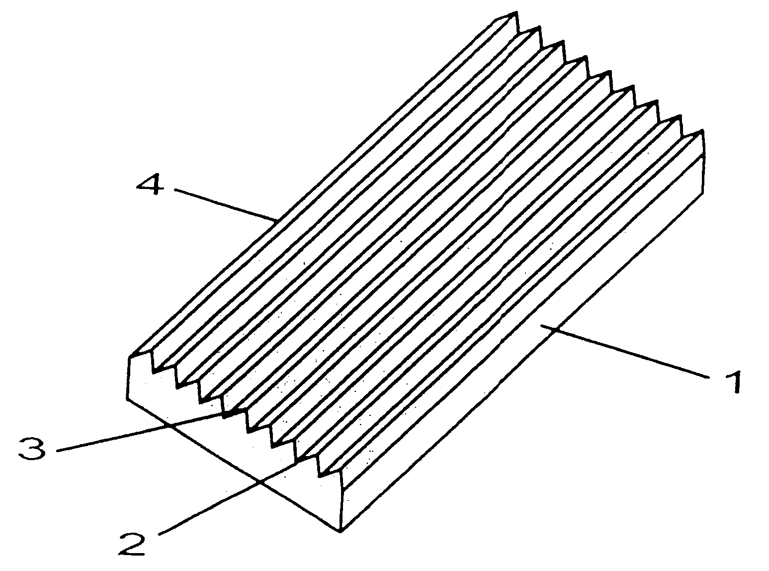
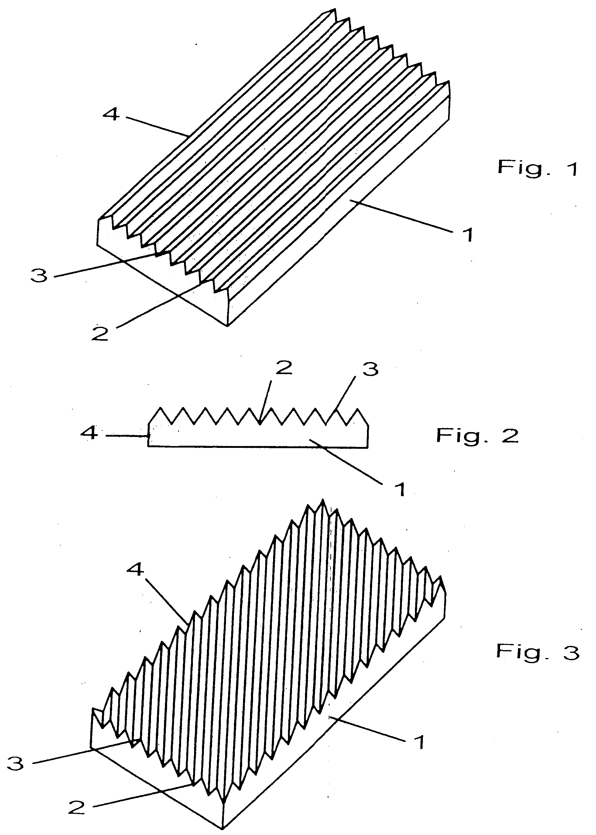
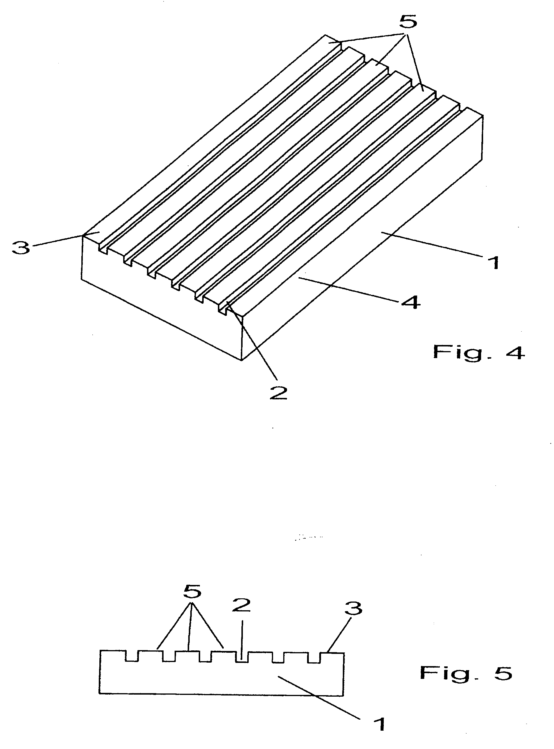
[0011]In FIGS. 1 to 5, insofar as individually illustrated, reference character 1 identifies a concrete slab that exhibits a longitudinal and a transverse extension and is fashioned as a rectangle. The concrete slab was fabricated by one of the shaping methods described herein, wherein the die associated with the concrete slab or the matrix in the corresponding working system has grooves and tooth strips that form corresponding grooves 2 and tooth strips 3 on the surface of concrete slab 1. Slabs 1 can, however, also be fabricated with planar-surfaced dies, grooves 2 being fabricated by a milling operation. In correspondence with the disposition of grooves and tooth strips on the dies, the grooves 2 and the tooth strips 3 on concrete slab 1 have exhibit arbitrary shapes and designs. Grooves 2 and tooth strips 3 of the concrete slab according to FIGS. 1 and 2 are aligned parallel to one longitudinal edge 4 of concrete slab 1, while grooves 2 and tooth strips 3 on the surface of concr...


PUM

PropertyMeasurementUnit
sizeaaaaaaaaaa
angleaaaaaaaaaa
triangular shapeaaaaaaaaaa

Abstract

A method for shaping concrete blocks and / or concrete slabs of various formats and sizes. The shaping taking place in concrete-filled molds with or without additional facing concrete. Dies or matrices corresponding to the block surface or slab surface have recesses or projections for impressing the surfaces. The concrete blocks or concrete slabs are then removed from the molds before setting and are cured externally and the surfaces are further worked in a subsequent operation. The recesses formed are grooves having parallel, oblique, planar or curved walls and / or roots and the projections being tooth strips having parallel, oblique, planar or curved walls and / or tips. The grooves and / or tooth strips extend over the entire surface of the dies and consequently over the entire surface of the concrete blocks or concrete slabs. In a subsequent operation the surfaces are blasted with liquids or solids. A final step may include application of a coating containing acrylate resin.

Description

BACKGROUND OF THE INVENTION[0001]The invention relates to a method for shaping concrete blocks and / or concrete slabs of various formats and sizes. A method for fabricating and / or working concrete blocks is known from European Patent 0 319 972 B1, which discloses dies having recesses or projections that are randomly distributed over the die area and form a reciprocal surface on the concrete blocks. In a subsequent operation the surfaces and, as appropriate, also the edges of the concrete blocks are cleaned of loose parts and additionally roughened or damaged. Concrete blocks or concrete slabs having a rough surface with small departures from planarity but no ribbed or broached texture are obtained by the known method. Further, a method and an apparatus for artificially aging concrete blocks are known from German Patent DE 36 21 276 A1, where cured concrete blocks or concrete slabs are worked with a chisel-like striking tool so that an irregularly worked surface is produced.BRIEF DESC...

Claims


Application Information

Patent Timeline
Patent Type & Authority Applications(United States)
IPC IPC(8): B28B7/22B28B7/20
CPCB28B3/021B28B7/0082B28B11/044E04F15/08B28B11/0863E01C11/24B28B11/0818E04F15/02161Y02A30/60
Inventor METTEN, HANS-JOSEF
Owner METTEN STEIN DESIGN
Learn More